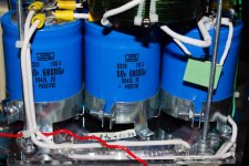
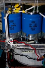
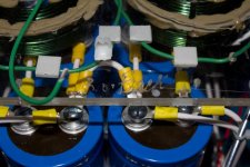
I understand you Bob, and I thank you all guys, sorry if I misleading you when I said left and right bridges , just saying the position they have on the chassis.But, since JPDuarte has been so ambiguous about what wire goes where, specifying his right and left without knowing what leads he has there may lead him to miswire it. Let's wait until he verifies the connections before we tell him anything. Remember that we are not dealing with an experienced builder, what is easy and obvious to us doesn't seem so to him.
JP - the last time I blew up an output stage I was absolutely sure that the fets were matched to within .01V Vgs that I couldn't understand why it blew until I pulled it apart and saw that I had ignored the .1V place on the Vgs label meaning that one device turned on .1V lower than the rest and was taking all the current. I'd been so careful. I also color coded the PSU leads I soldered to my first Leach amp boards. Three of four channels worked fine. One kept instantaneously blowing up the limiting resistors in the rails. After many hours of troubleshooting verifying every value and part orientation, I finally noticed that I had reversed the power supply leads. Swapped them and the amp has worked fine for over 10 years.
The point of this is when trouble shooting assume nothing is correct. We cannot see your amp, so you have to carefully tell us what we ask for.
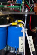
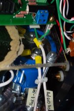
Yes, They Are.Are these the wires paired to connect to one of the bridges?
.
Please don't be mad. Thanksi'm out. jp. PM me if you need anything
Your are 100% correct.Are these the wires paired to connect to one of the bridges?
Ambiguity alert - I hope that you don't mean right and left bridge. I took this to mean that the black wire on the left in this photo connects to the negative terminal of the cap bank and the red wire on the right in this picture connects to ground.
He's just mad at me, I'm generally too blunt for a lot of people, but I usually get my point across.
Please don't be mad. Thanks
i'm not mad at you🙂 i'l help you anyway i can. i'm building the same amps myself. so i now them a bit🙂 not the same PCB's. but the PSU is the same.
Ok, I' do it .OK, now verify the other pair are of the correct polarity.
Yes, I just noticed 😀He's just mad at me, I'm generally too blunt for a lot of people, but I usually get my point across.
So you have identified and labeled the wires running to the other bridge as going to ground and the positive side of the cap bank?
If so, connect them appropriately. The positive bank plus terminal goes to the positive terminal on the bridge, the negative terminal on that bridge goes to ground. The negative bank terminal connects to the other bridge's negative terminal and that bridge's positive terminal to ground.
Now use your variac to test at maybe 10%. Here you are going to clip your meter's black lead to ground and use the red lead to verify that the positive bank of caps is going to a positive voltage and the negative cap bank is going negative to pretty close to the same magnitude.
Once you are sure that the voltages are going the right direction, turn the variac up to 100% and measure the rails without moving the meter's black lead from ground.
The inductor's loose connections could very well have caused a lot of issues, but we'll keep proving this one out.
Last edited:
Bob - I nominate you for the DIY "Most Helpful Buddy (MHB)" award for 2010! 
JP - Hang in there dude! At one time or another we have all been wrapped around the axle and wondering how in the heck we are gonna get the technical knot untied. Don't sweat it - UR do'n fine and it will all work out.
Blowing some of the "magic smoke" outta electronic devices is a humbling experience - but we have all been there so don't feel alone. The most important thing to remember is SAFETY!!! You are playing around with some voltages that can get to you - as well as things that can explode!! Know where the "off switch" is at - wear eye protection!
At some time in the future Bob will be able to call upon you for a favor of his calling. Pray that it's a technical one 😉
Attachments
Last edited:
An IMPORTANT! finding , connections to both inductors were lose . Already fixed.
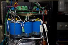
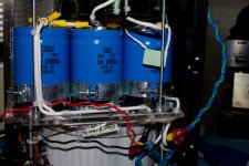
JD. i did ask you to check inductor coils🙂 at the same time. make sure there is no short from the inductors to the caps. it seems they are very close.
Yes I know , about inductors-caps distance no worries there's 1" of separation but at the photo you see this short distance.JD. i did ask you to check inductor coils🙂 at the same time. make sure there is no short from the inductors to the caps. it seems they are very close.
Yes, I did.So you have identified and labeled the wires running to the other bridge as going to ground and the positive side of the cap bank
- Status
- Not open for further replies.
- Home
- Amplifiers
- Pass Labs
- My Dream Aleph 2 Coming True

