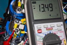
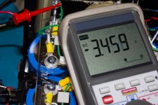
Going to do that.Now use your variac to test at maybe 10%. Here you are going to clip your meter's black lead to ground and use the red lead to verify that the positive bank of caps is going to a positive voltage and the negative cap bank is going negative to pretty close to the same magnitude.
Disconnect the Bridges from the caps. Review where the wires go to the bridge feeding the positive rail. Sounds like you have them backwards.
Verify that the the bridge is connected properly - with the black lead of your meter on the negative lead and the red to the positive do you get a positive voltage reading?
Once you correctly identify the leads to the PSU and that the bridge works properly, hook them up and try again.
Verify that the the bridge is connected properly - with the black lead of your meter on the negative lead and the red to the positive do you get a positive voltage reading?
Once you correctly identify the leads to the PSU and that the bridge works properly, hook them up and try again.
But remember I did that before and was ok. 😕Disconnect the Bridges from the caps. Review where the wires go to the bridge feeding the positive rail. Sounds like you have them backwards.
Either the bridge is backwards or your connections to the positive caps are reversed. So, time to back up and check.
Confuse here, when you say negative and positive lead , are you talking about positive and negative lead of the bridges ? right ?Verify that the the bridge is connected properly - with the black lead of your meter on the negative lead and the red to the positive do you get a positive voltage reading?.
Now go back and recheck the wires leading to the positive side bridge. Chances are that they are reversed from what you thought they are.
Bob, not being there to see first hand may I suggest that possibly the secondary winding that feeds the pos bridge is bad, and the bleeder resistors are feeding some neg voltage to the pos side, seeing that the bleeder resistors are connected from rail to rail and not to ground.
It would be nice to know how much current the primary is pulling.
If it is not miswiring at fault here, I would say it is time to load test the trafo and bridges. It's pretty difficult to do it long distance, but you seem to be doing quite well in that regard.
It would be nice to know how much current the primary is pulling.
If it is not miswiring at fault here, I would say it is time to load test the trafo and bridges. It's pretty difficult to do it long distance, but you seem to be doing quite well in that regard.
Good point Bill.
JP - Do you have any spare 1W+ resistors that you can use for bleeder resistors? Move the one you have to connect negative rail to ground and then connect a new one from positive rail to ground. That will isolate the supplies and ensure that the negative supply is not affecting the positive. As mentioned before, if you have a bunch of 10-20K 1/4W resistors, you can make a TEMPORARY bleeder with a group of them in parallel.
What did your bridge lead tracing turn up? Did you do a continuity check? Measure the resistance from the bridge connector to the rail and to ground respectively. Depending on where you measure the rail, you may be including the DC resistance of the inductor, so don't panic if it is not zero. You should see a low number, though.
Just double checking, what does your meter give you for each secondary winding of your transformer (disconnect from the bridges to measure)? They should be very close.
What have you got in your parts box for power resistors?
Good point Bill.
JP - Do you have any spare 1W+ resistors that you can use for bleeder resistors? Move the one you have to connect negative rail to ground and then connect a new one from positive rail to ground. That will isolate the supplies and ensure that the negative supply is not affecting the positive. As mentioned before, if you have a bunch of 10-20K 1/4W resistors, you can make a TEMPORARY bleeder with a group of them in parallel.
What did your bridge lead tracing turn up? Did you do a continuity check? Measure the resistance from the bridge connector to the rail and to ground respectively. Depending on where you measure the rail, you may be including the DC resistance of the inductor, so don't panic if it is not zero. You should see a low number, though.
Just double checking, what does your meter give you for each secondary winding of your transformer (disconnect from the bridges to measure)? They should be very close.
What have you got in your parts box for power resistors?
Sorry for the delay, and yes i have some 1,2,3 and 5 watts resistors but how many ohms. I'll do everything you say when get home, right now at work. Thanks
I don't know how close that storm is to JP. He might have lost power already.
Hi Bill, Are you profiling ? thanks god the storm is far way from here, by the way is closer to you than me. Again thanks for your great advise like always. JP DUARTE.
Ok guys I did a continuity test to the inductor connected to positive rail and founded a ring terminal to one of the inductor lead was completely loose no connection whatsoever. Do I found the solution to all my problems, will see .
JP, I never did trust the insulated crimp connections, most of them are junk. I have even removed the insulation from them and soldered the lugs on many occations. In the future I would recommend using uninsulated connectors, solder them on, and use shrink tubing to insulate them. Pretty foolproof that way.
Yes, your right, hooked again the amp to measure rail and again positive rail having problem , then move inductor connection and got the right measure, going to solder those connection and post later. Thanks Bill.JP, I never did trust the insulated crimp connections, most of them are junk. I have even removed the insulation from them and soldered the lugs on many occations. In the future I would recommend using uninsulated connectors, solder them on, and use shrink tubing to insulate them. Pretty foolproof that way.
we use them in our railroad signal houses to go from relay to relay. i had a cir get hit by lighting and one of the eyes worked like a diode after that. it took a week and 3 guys who had forgot more stuff than ill ever know to find it. i kept it for years, to show guys who didnt belive us. it finaly went open. every time since i do as bill said.
good find i hope that fixes it
good find i hope that fixes it
update
Last night after having problems with inductors rings connector, I did solder 4 inductors leads , think I solve voltages problems that was having with positive rail. I started taking some measurements according to Pass Labs schematics and they were very optimistic , when I get home, are going to post all of them for your consideration.
Last night after having problems with inductors rings connector, I did solder 4 inductors leads , think I solve voltages problems that was having with positive rail. I started taking some measurements according to Pass Labs schematics and they were very optimistic , when I get home, are going to post all of them for your consideration.
- Status
- Not open for further replies.
- Home
- Amplifiers
- Pass Labs
- My Dream Aleph 2 Coming True

