Krisfr
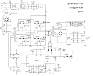
I found this on web,might help since you are intent on FB,see attached photo.I don't know if it works but idea is sound.Also if you want you can down load LTspice and simulate your IGBT's in a circuit to see if they work or not, of course you will need the spice model for the device.
I found this on web,might help since you are intent on FB,see attached photo.I don't know if it works but idea is sound.Also if you want you can down load LTspice and simulate your IGBT's in a circuit to see if they work or not, of course you will need the spice model for the device.
Attachments
Last edited:
I looked at the datasheet from IR and also found the spice model on thier website,it looks like the best you can expect is about 35kHz for a hardswitch,however they claim upto 200kHz in resonant operation.I loaded device into LTspice and did a quick sim at 50kHz seem to work ok,hope this helps...
I really like the schematic, it is very close to what I want to do.
I will be using 110V not 220 and I will try to modualize this so I can try different topologies.
Building instead of talking needs to be on my table. I got some other ideas for the soft start and parts are in the mail to me to get started soon. I will get off my duff and get SOMETHING done here.
Thanks to all especially Chas1 and Luka...I think I am in good and intelligent company that shares a lot of knowledge and I hope to return the FLAVOR.
One more important area...
The High Current input and Output (Filter-Inductors)
Are they hard to build? I think I am looking at 10 turns each in opposite directions for the input one of what 14 gauge or 12 gauge or 10 gauge around a ferrite core. What would be the PHYSICAL size of the core? Can that same CORE be used with appropriate wire gauge for the output?
The current sensing core I think I can fab out of some Personal Computer power supply ferrites I have.
I have to play around with the SG3525 just to get a feel for its idiosyncrasies... it has been a long while since I played with a PWM circuit.
My input control circuit is a zero cross detect with a switch selected control of a 555 to slowly switch on a back to back SCR activated AC voltage source.
I will use a conventional small transformer to develop and use 12 volts to control the PS system.
I am going to go back and look at your development bread board Chas1 and see if I can glean some wisdom... Thanks for sharing...
inductors you can do yourself, if you feel up to it. I did my own, but input one is questionable, I don't remember if I used one of the cores from the input of broken PC supply, there was also output one taken from there.One more important area...
The High Current input and Output (Filter-Inductors)
Are they hard to build? I think I am looking at 10 turns each in opposite directions for the input one of what 14 gauge or 12 gauge or 10 gauge around a ferrite core. What would be the PHYSICAL size of the core? Can that same CORE be used with appropriate wire gauge for the output?
The current sensing core I think I can fab out of some Personal Computer power supply ferrites I have.
I have to play around with the SG3525 just to get a feel for its idiosyncrasies... it has been a long while since I played with a PWM circuit.
My input control circuit is a zero cross detect with a switch selected control of a 555 to slowly switch on a back to back SCR activated AC voltage source.
I will use a conventional small transformer to develop and use 12 volts to control the PS system.
I am going to go back and look at your development bread board Chas1 and see if I can glean some wisdom... Thanks for sharing...
It will help if you have way of measuring inductance, or you will have to do it the hard way and calculate(but core must be known at that point).
Wire size will depend on current, but you can play with this, if wire heat up too much, or if you have too big one and its cold, but can't get enough turns on core... play it with, fun part right there 😛
Also doesn't need to be AC supply right away, you can always just put lower voltage in, AC or DC. If you can power SG, then any input voltage will do, it will be safer for you + you can play with circuit in anyway you like without risk of

LUKA`S SMPS still rock`in ......................... you`re good :d
Luka, i want to share, until now im still using irf740 2 pcs for your smps but i`m just little bit confuse, i`m powering 2 channel dx-amp with no heat at all on mosfet... power transformer get hot but not too much and 15A 600v from my 240 vac also getting little hot.. that dx-amp has been moding with uncle Charlie guide and run at +50 0 -50 rails. with 8 power transistor 4 pcs 2SA1302 and 4 pcs 2SC3281 hitting 4 pcs 15 inch speaker easyly.
I think this smps can produce more power using only irf740, i would like to ask you with your opinion, im plan to build another one what i have with me now is 2SK2698 toshiba i`ve got this from my friend electronic welder old and never use so i take the power tarans, also i have FDA20N50F and STW14NK50z all this chips suiteable for this smps?
Regards,
Azmi.
If you have AC meter, you could check input current, but it has to be TrueRMS or reading will be wrong. If you don't have that, you can put resistor in series with AC, 0.1 to 1R, in the neutral return line, and look at current there. Just put probes of the meter on each side.
If your trafo is heating up, you have low or too low primary turns count and you are running it close to saturation (you might want to change this).
But it's still odd, my bridge rectifies never heats up, never had, on the heatsink that was in the picture on my site and here
Maybe you can post picture, to see how your setup looks like
hasnt anyone found a simple protection schema yet?
steve
Depends on IC controller chip,but most have a pin that if the proper voltage is applied the controller will shut
down and if you check the appnote for that ic more than likely there will be a test circuit that demos it use.
Last edited:
I am getting it started up in here.
Thanks for all the input, this is going to be a FULL BRIDGE at 110 V.
Please point out any thing that I may be going wrong on.
Thanks
Thanks for all the input, this is going to be a FULL BRIDGE at 110 V.
Please point out any thing that I may be going wrong on.
Thanks
Attachments
Last edited:
Lot of caps,no inductor and from your specs it's size will be large(physical),you should also watch out for ESR approaching zero with that many caps,if that happens stabilty problems will exist for load changes and regulation will suffer.(hard to compensate)
you really don't need that many caps, unless you will drive 200A output, where multi phase output would be 1000x better. If you'll do it the right way, regulation will take care of everything(stabile output voltage). So you need output inductors and less caps(depending on size, 3-5 could be enough), Also I would like to see half that big board, and if possible, 2 sided
What will be the output voltage/current rating? singe output?
What will be the output voltage/current rating? singe output?
Questions
I think you should take time out and read thru the whole thread very careful and learn from others,an smps is a controller with feedback loops and certain rules have to be understood and followed or you risk damages to what ever load you intend to add to the output.There are many posts by EVA addressing the pitfalls of layout,di/dt problems and proper gate drive along with other useful info and once you have done that post a clear design requirement along with a schematic and pcb layout ,remember mesaure twice and cut once and by the way only one well designed inductor will be needed (two windings opposing phase on a single core,properly chosen)
I think you should take time out and read thru the whole thread very careful and learn from others,an smps is a controller with feedback loops and certain rules have to be understood and followed or you risk damages to what ever load you intend to add to the output.There are many posts by EVA addressing the pitfalls of layout,di/dt problems and proper gate drive along with other useful info and once you have done that post a clear design requirement along with a schematic and pcb layout ,remember mesaure twice and cut once and by the way only one well designed inductor will be needed (two windings opposing phase on a single core,properly chosen)
Last edited:
Direction
This was the direction that I am headed in...
diysmps
Did not know you had to be a member to see this. SORRY...
it looks as IF the input and the output inductors are on separate cores...
I do not know if this one works but it looked good, so I said to myself what the hell.
Can someone tell be the source of not too expensive Toroidal Cores that would be suitable for this project.
I wanted to play at it,with it before committing to a double sided board... IS THAT OKAY? I saw what you did, Chas1, near the start of this thread, I think in post #246, and wanted to do the same.
Well I have SG3524's in house and will fire one up to see what the O-Scope has to say about this SMPS stuff. I have on played with a PWM in about 25 years. Wish me luck. Bread board here I come.
I got a heatsink ready for the testing. I will post the drive circuit of the IGBT a little latter if I don't get to involved in the SG3524. The drive transformer is on order from Mouser.
Bmax for those 3c90 and 3f3 is not more 400, where did they get the 1200 from?
Flux can be in Gauss or in Teslas.
400 mT = 4000 Gauss.
new halfbridge
Luka
I am in the startup phase of an LLC HB converter,these supplies require a stable bulk supply and a PFC is recomended.I have read thru quite a few datasheets from ON and Fairchild and just about finished a simulation in LTspice and so far so good.1st Goal is about 500watts (+/-50VDC@5amps)want to join in.Might have to start a new thread,the goal is 1kW....???.I will post sim files and schematic later this week.😎😱
 😕🙄
😕🙄
Luka
I am in the startup phase of an LLC HB converter,these supplies require a stable bulk supply and a PFC is recomended.I have read thru quite a few datasheets from ON and Fairchild and just about finished a simulation in LTspice and so far so good.1st Goal is about 500watts (+/-50VDC@5amps)want to join in.Might have to start a new thread,the goal is 1kW....???.I will post sim files and schematic later this week.😎😱
😕🙄Cool I'm in!!Luka
I am in the startup phase of an LLC HB converter,these supplies require a stable bulk supply and a PFC is recomended.I have read thru quite a few datasheets from ON and Fairchild and just about finished a simulation in LTspice and so far so good.1st Goal is about 500watts (+/-50VDC@5amps)want to join in.Might have to start a new thread,the goal is 1kW....???.I will post sim files and schematic later this week.😎😱
Got PFC figured out? I have found that with it and on none regulated suppy, output was very stabile, with regulation << 50mV response on big step load. This should be interesting, go for it!
- Home
- Amplifiers
- Power Supplies
- Offline full-bridge SMPS… need help