Feedback causes them linearizing transfer curves. Phase shifts in feedback loop cause uneven sidebands of intermodulation (really nasty, lifeless, dry sound, like sand in the mouth!).
How would I measure this, and what input signal would I use? Wanna try it in the simulator...
- keantoken
How would I measure this, and what input signal would I use? Wanna try it in the simulator...
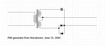
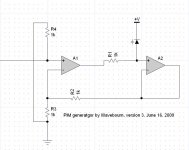
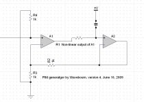
Try this:
Attachments

Member
Joined 2009
Paid Member
I'm afraid that I am developing one of those prejudices that seems to afflict people in this hobby from time to time. I'm not liking much about gnf.
It appears to be necessary to cover up for cross-over artifacts in Class AB (desired for power efficiency/lower cost) and to make non-linear amplifying devices behave collectively in a linear fashion. Feedback is also used to achieve higher damping factors, allowing the use of high power amps driving inefficient speakers that need lots of control.
But when you use nfb you create an amplifier that has a lot of complex issues and it requires a good design to avoid a nasty sound. Good design seems to mean different things to different people, but it appears difficult to match up measurements with perceived sound.
All in all it would seem to make for an easier life to avoid nfb. This means using amplifying devices that are as linear as possible (tubes for now, power JFETs in the future - are the key contenders in my mind). It means using efficient speakers so that signal levels can be lower, cone movements smaller and to allow the use of Class A with it's inherent inefficient power use.
I don't know much about Class D and where it fits into this.
All in all it would seem to make for an easier life to avoid nfb. This means using amplifying devices that are as linear as possible (tubes for now, power JFETs in the future - are the key contenders in my mind). It means using efficient speakers so that signal levels can be lower, cone movements smaller and to allow the use of Class A with it's inherent inefficient power use.
It's like everything else, you gain something; you lose something. Avoiding gNFB doesn't make life any easier. What you give up when you give up gNFB is the relative independence of performance from passive and active components. How the end product sounds becomes highly dependent on selection of VTs (especially since these are low gain devices) and passives, especially capacitors, and the sort of load the speeks present to the output. That's where tube rolling and controversies over PiO, polymer film dielectrics (polystyrene, polypropylene, etc. ) Teflon comes into play. Open loop performance becomes highly dependent on all of these things. That's one of the reasons gNFB was used in the first place: it shifts performance from the components to the feedback loop.
I don't know much about Class D and where it fits into this.
Class D amps can use the same sorts of NFB: local, global, or no NFB. (Excluding the feedback necessary to make the PDM for the finals, of course.)
This one is more interesting: very low THD, but very nasty sound.
LOL Great illustration!
Any time you introduce slew limiting, or more evil, asymmetric slew limiting, inside a feedback loop, of course there is a problem.
The open loop gain bandwidth of the amplifier needs to be greater than the signal bandwidth.
What is the THD near the open loop corner frequency?
It is just an illustration of what happens on more subtle level.
What is bandwidth? It is like a waist line on a dress. You can put it higher, you can put it lower, but if the person does not have a real waist due to body structure it may be anywhere you wish. And you know, no amp has a real waist, only imaginable one! You can set some imaginable limit if your tool allows more precise measurements, or you can say that what your tool can't measure does not matter. Like, does not matter if we hear below noise floor: everything below noise floor according to standard measurement practice does not matter. Even when it is perceivable by human hearing!
So, how to find if the dress has higher waist line that the human that supposed to wear it, if neither dress, nor human being have one? How do you put a waist... sorry, a bandwidth to the signal? And how do you put it on the amp?
So, it illustrates what happens to an amp that has in-band phase shift, and some non-linearity. And it has, you know! Linearizing the amp with feedback you turn linear phase shift to non-linear one, modulated by the signal. Now you can measure say -180 decibel of total sum of harmonics, but the amp will sound nasty...
...and people who like to read smart literature in order to get smarter would have a very simple explanation: "You guys don't like clean non-distorted sound! You like sound of your tubes because they add euphoric distortions!" 😀
Last edited:
I guess by people you mean me, as I'm people 😉 I meant that it goes round and round.
It must go round and round because it's fed back, in a loop. The output is fed back (hence the term feedback!) into the input. If you can detect that feedback is in use then it must be changing the output, which in turn gets fed back to the input. From there it works its way through that amp to the output and gets fed back to the input. And round and round it goes.
OK you say, but each time around the feedback artifacts get much quieter so it doesn't travel round and round for long. Well yes and no, it will travel round until you hit the noise floor deep enough to be dissipated. How audible it is on say the 3rd time around will depend on factors of course.
In theory I guess it doesn't go round and round. But in that theory I think you also have a linear amplifier with zero time delay. As soon as you look at a real non-linear amp with a time delay between the input and the output that theory becomes junk.
The non-linearities will give you the multiplication of harmonics, the time delay will give you phase shifts that vary with frequency. Negative feedback is all about correcting the input signal by comparing it to the output signal. When the output signal is for instance travelling through the amp you cannot compare it properly because it is delayed in time.
Have a read of the Audio Note page here which has an interesting take on the overload effect of negative feedback due to the time delay it takes the signal to transit the amplifier.
The design practices most obviously eschewed in the development of the Audio Note Real Audio amplifiers (using direct heated power triodes) is the use of negative or local feedback. Negative feedback, quite simply, is the application of an inverted portion of an amplifier's output signal to its input terminals. This "extra" signal is subtracted from the input and serves to reduce the effective amplifier gain (as the input signal is then smaller). In addition, steady state distortion is thought to be reduced as the out-of-phase distortion components contained in the feedback signal cancels out some of the errors created by the amplifier circuitry.
This scheme presents two very obvious problems. Firstly, all amplifiers introduce some delay to passing a signal from its input, to its output and then back to its input. During this delay period, a feedback amplifier is operating at its natural (referred to as "open-loop") gain. It is not until this initial delay period is over, that the circuit begins to exhibit its intended operating ("closed loop") gain characteristics. There must be, by the very definition of a feedback system, some change in the gain factor G, during the transition from open to closed loop operation. This gain modulation would probably not be audible by itself, as the propagation delays of most good amplifiers are quite small, except that the increased gain of the amplifier during the initialization period results in a decreased maximum input capability before overload. Simply put, an amplifier which utilizes 20 dB of feedback (a relatively modest amount by modern standards) and requires an input of two volts to clip during closed loop operation, would overload with only two tenths of a volt input during the forward delay period. Once the amplifier is overdriven, it may take many times its delay period to become fully restored to normal operation. The distortion created by this condition has been commonly referred to as Transient Intermodulation Distortion (TIM), Dynamic Intermodulation Distortion (DIM), and Slew Induced Distortion (SID).
In addition to this obvious form of feedback induced distortion, there exists another more subtle effect of signal regeneration. Because all amplifiers have some forward propagation delay, the fed back portion of the output signal will always lag behind the input. There is therefore a constant introduction of "out of date" information into the amplifier. Under transient conditions (which is what music is; transients), this results in the presentation of an error correction signal intended to reduce the distortion of an input signal which has already passed through the amplifier and is either already out of the circuit or well on the way out of the circuit. The signal present at the input by the time the feedback has arrived may bear no relation to the previous signal and thus will not be properly acted upon by the regenerated information. The current input signal is then distorted once, through the subtraction of an erroneous feedback waveform, and again by the amplifier. Additionally, the error signal present in feedback is passed through the amplifier and again fed back, with all of the newly created distortions, to make yet another trip through the circuit, until it is allowed to decay through successive attenuation. Thus, a distortion signal which originally may have lasted only a few microseconds, can pass through the amplifier enough times for its effective duration to have exceeded the threshold of human audibility. The mechanism originally designed to reduce audible distortion, actually, under transient conditions, serves to regenerate, emphasize and, in fact, create distortion.
Because our Real Audio triode amplifiers operate totally without signal feedback, such distortion regeneration does not take place. The circuits have been designed for maximum linearity without corrective mechanisms, and thus responds as easily to transient signals as it does to steady state waveforms. The amplifiers make no attempt to reverse the path of time in order to correct their own errors. Those distortions created by these circuits (which are almost entirely harmonic in nature) are allowed to pass only onto the loudspeaker, and not back to the input.
Despite the absence of feedback, the forward propagation delay of all our amplifiers has received much attention. All our output transformers have been designed using this criterion, obviously with a keen eye on cost. It is obvious that if this delay is not absolutely invariant, for all conditions, the DeltaT component of the input signal will not be accurately preserved. Thus, those factors which determine delay have been carefully observed and stabilized. In addition, the operation of all amplification stages at nearly constant power, independent of signal conditions, i.e. Class A operation at every stage, greatly contributes to the symmetry and linearity of our circuits.
That's from an advertisement on the AN website written by Peter Qvortrup, who posts on this forum occasionally.
I'd like to see some measurements and scope shots of the feedback error cycling through a well designed amplifier under normal operating conditions and decaying out over tens of microseconds.
This whole take on feedback assumes that the propagation delay is significant in the audio band and this is only true IME for amplifiers which are band-limited relative to the signals they pass.
TIM distortion is real, as I have known since the early 1980s when I discussed the matter with Susumu Takahashi, a Sansui engineer who characterized the problem in terms of slew limiting. But it is not induced solely by feedback. It is caused by trying to use feedback to correct a bandlimited amplifier.
Wavebourne's circuits illustrate the problem. However, if the flat-gain passband of the amplifier in open loop is some small multiple of the band-limited audio passing through it, the delay-induced IM distortion should not be a problem.
I guess I take exception to the notion that delay is always a problem and all feedback is bad. If the amplifier has enough bandwidth, the feedback signal will keep up because the audio signal from the program source can only slew so fast. Please read the literature on TIM distortion from Otala and Takahashi for a rigorous treatment.
I also allow that an OPT with a group delay longer than a few microseconds would likely be a candidate for causing TIM problems inside a NFB loop.
The harmonic multiplication effect is also real but another matter with different effects.
Cheers,
Michael
Mike I fully agree with your take on this. Yes slew rate limiting CAN be a problem but it has been known for decades how to design an amp free of SR limiting. Intuitively, if all the nodes in your amp can slew significantly faster than any realistic musical input signal, the amp can always follow the signal very closely. There will be no case of overshoot, and certainly no case where the amp temporarely reverts to open loop operation while waiting for the feedback to complete it's path.
Take the analogy with you at the rudder of a very large ship. You need to steer the ship along a straight line. You can say, that you can only react to the course deviations AFTER they appear, but your reaction (the speed of you being in the feedback loop) is so much faster than any course deviation of the ship that you can steer it perfectly along a straight line. Of course if you look deep enough you see wiggles along that course, but the crucial thing is that these wiggles are much, much smaller than when you used a non-feedback steering system. In fact, just like amps, you'd need specialized test equipment to see the deviations at all!
As you go up in frequency, the amp's phase shift causes the fed-back signal becoming progressively phase shifted to the input signal. What that means is that the cancellation of the portion of the output signal (including distortion) with the input signal gets less complete: the two signal waves are no longer perfectly aligned and subtraction leaves a larger residue. Therefore, the non-cancelled portion increases with frequency and that leads to less effective feedback with rising frequency, meaning less distortion reduction with rising frequency.
It's really all very simple. Sorry I can't make it more sexy than that 😉
jd
Michael Koster / Wavebourn.
Those distortion curves looked very familiar - a quick wade thru' the pile of papers and I found that graph.
Wireless World December 1978
"Audio power amplifier design - 5" by Peter J Baxandall
In which he shows mathematically:
1) 6dB of global feedback will reduce 2H by about 6dB at the expense of increased higher order distortion
2) 16.5db of global feedback is required to reduce the 3rd harmonic back to the no global feedback level
3) 35dB of global feedback is required to reduce the 6th harmonic back to the no global feedback level
I have a pdf of that article. PM me if you want it and can't find it on the web.
I recall Allen Wright saying that his "guru" told him that global feedback needs to be 40dB or NONE.
Personally I like none.
Cheers,
Ian
I also allow that an OPT with a group delay longer than a few microseconds would likely be a candidate for causing TIM problems inside a NFB loop.
That's interesting, that also ties up (in a sort of related way) with a long thread on here (can't seem to track it down now) by a member with an oriental three-word name who made a very good case for keeping the OPT out of the feedback loop.
His basic premise was that to improve any given OPT you took it out of the loop and instead concentrated any NFB on the driver/output tubes to lower the impedance presented to the primary. I.e control the primary with authority and the OPT will take care of itself, and in a better way than using feedback because you were not just getting bandwidth by squashing the open loop gain (as the bandwidth with a cheap OPT would be limited at open loop anyway) but actually driving the bandwidth through the OPT.
It does seem to make for a good sound too, taking my OPT out of the loop and lowering the impedance of the driving stage (via NFB over driver + output tube) has only had positive effects.
Michael Koster / Wavebourn.
Those distortion curves looked very familiar - a quick wade thru' the pile of papers and I found that graph.
Wireless World December 1978
"Audio power amplifier design - 5" by Peter J Baxandall
In which he shows mathematically:
1) 6dB of global feedback will reduce 2H by about 6dB at the expense of increased higher order distortion
2) 16.5db of global feedback is required to reduce the 3rd harmonic back to the no global feedback level
3) 35dB of global feedback is required to reduce the 6th harmonic back to the no global feedback level
I have a pdf of that article. PM me if you want it and can't find it on the web.
I recall Allen Wright saying that his "guru" told him that global feedback needs to be 40dB or NONE.
Personally I like none.
Cheers,
Ian
The Baxandall curves, IIRC, are from a single FET stage, with a specific non-linear transfer characteristic. While the basic effect is real in any non-linear amp, people like Bob Cordell have shown here that it is very different for other topologies. It is possible to have circuits where the effect can only be seen at very, very low levels.
jd
That's interesting, that also ties up (in a sort of related way) with a long thread on here (can't seem to track it down now) by a member with an oriental three-word name who made a very good case for keeping the OPT out of the feedback loop.
Maybe this thread?
http://www.diyaudio.com/forums/tube...ective-global-fb-decent-damping-factor-2.html
Taking the OPT out of the loop will certainly help with stability. The downside is that you have to live with whatever distortion the OPT itself produces.
GNFB is less necessary for reducing crossover distortion than many people think. This is because crossover distortion is less necessary than many people think. You can't eliminate it completely (from P-P), but you can make it small by choosing correct bias. I think most people run their outputs too hot, because they want to run in Class A for small signals. The result is more crossover distortion at middle-level signals. See the stuff by Douglas Self on "gm-doubling" - although written for solid-state it can be applied to valves too. Note that the correct bias for P-P depends as much on the circuit topology as it does the actual devices used. Roughly speaking, you want the gain of each output side at zero crossing to be about half what it is for signal peaks (when the other side is more or less cut off).
There is some truth in the extra problems of feedback when an amplifier has delays, but I think these are often exaggerated. Few amps have a pure delay, except perhaps in the ns region, but most have many HF rolloffs. This means that the feedback starts to operate immediately but takes time to have full effect. You do need to avoid overload, slew limiting, and excessive distortion during this time but talk of transients lasting a few microseconds forgets that the input signal is already band-limited and high frequency transients tend to be small compared with mid-frequency signals. There are three places where fast transients can be a problem: phono preamps playing dusty records, DAC buffers, and anything following a NOS DAC. As small-signal valves are generally better at handling big signals at high frequency than small-signal semiconductors this may be partly why valves sound better here.
I think most people run their outputs too hot, because they want to run in Class A for small signals.
Both phases conducting is *NOT* class A, it is just a part of it, the primary being that both phases are conducting at full power. If you get one side cut off prior to reaching full power it is either AB or B.
The AB and B bias also needs to account for a halving of the load as one side gets cut off. The load goes from a-a/2 under both side conduction to a-a/4 once one side is cut off.
If the lower power( v. AB or B ) and efficiency can be tolerated Class A is worth the effort.
cheers,
Douglas
I accept what you say about Class A, but I was using it in the sense that many (mis)use it. If we are being careful, then I am unsure about the distinction between AB and B. Class B has to have some overlap otherwise there is crossover distortion. Does any overlap make it Class AB? If so, then Class B should never be used. If not, then AB must mean too much overlap so AB should never be used. Perhaps what I should have said is that people use AB where A or B would be better.
Could you clarify what you say about the load changing? Surely the load does not change, but the degree of assistance (not load!) offered by the other side varies. Having said that, I'm not sure I'm right so I need to think some more about it.
Could you clarify what you say about the load changing? Surely the load does not change, but the degree of assistance (not load!) offered by the other side varies. Having said that, I'm not sure I'm right so I need to think some more about it.
Class AB, optimally, is biased at the "null" point where for the given load and power, the transfer curves of both devices cancel the best. This is how I would characterize it.
- keantoken
- keantoken
Member
Joined 2009
Paid Member
The gain curves I've seen published show a wiggly line - there is no perfect cross-over with typical active devices. There was a design that did achieve a remarkable level of matching between the two P-P devices, I can't remember where it was but it was something to do with operating MOSFETs with a square-law transfer curve.
Kean - do you know about this ?
Kean - do you know about this ?
You are right that there is no perfect crossover, but there are optimal ways to do it.
I haven't messed with MOSFETs. I've heard the SPICE models don't simulate them correctly, so I'm reluctant to simulate. I have heard however that some FET-type device gets better crossover than BJT's.
- keantoken
I haven't messed with MOSFETs. I've heard the SPICE models don't simulate them correctly, so I'm reluctant to simulate. I have heard however that some FET-type device gets better crossover than BJT's.
- keantoken
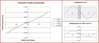
To study crossover distortion, I made a simple spreadsheet model using 3/2 power curves to build a composite curve.
I believe the desired gm behavior is: at crossover the composite gm should be the same as one device just as the opposite device cuts off. Obviously this is true for class B.
I couldn't find a spot in AB with a smooth composite curve. Luckily, real tubes don't follow this exactly and some seem to match better through the crossover curve. It's hard to get the wiggles out...
But, it's a really simple model just to play with. I wouldn't even trust SPICE VT models to be good enough to nail this. I was simply hoping to gain some more insight.
PS Note that the error curves are referenced to the "ends" of the fransfer function i.e. the error is relative to a straight line connecting the full signal endpoints and bisecting the idle point.
Attachments
Last edited:
- Status
- Not open for further replies.
- Home
- Amplifiers
- Tubes / Valves
- global negative feedback schematic