That's interesting, that also ties up (in a sort of related way) with a long thread on here (can't seem to track it down now) by a member with an oriental three-word name who made a very good case for keeping the OPT out of the feedback loop.
His basic premise was that to improve any given OPT you took it out of the loop and instead concentrated any NFB on the driver/output tubes to lower the impedance presented to the primary. I.e control the primary with authority and the OPT will take care of itself, and in a better way than using feedback because you were not just getting bandwidth by squashing the open loop gain (as the bandwidth with a cheap OPT would be limited at open loop anyway) but actually driving the bandwidth through the OPT.
It does seem to make for a good sound too, taking my OPT out of the loop and lowering the impedance of the driving stage (via NFB over driver + output tube) has only had positive effects.
Totally! Use a really good OPT that can performs well open loop, select devices and op points for minimum open loop error, and use O.H. Schade style local feedback as needed to drive the OPT with low plate resistance.
At least that's my current approach until I find something better...
Cheers,
Michael
PS would that be the bright fellow who now goes by his european name?
Last edited:
Member
Joined 2009
Paid Member
use O.H. Schade style local feedback as needed to drive the OPT with low plate resistance.
And hence improve damping factor.
I use locals & global feedback, combined.
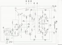
Here is an output stage:
http://wavebourn.com/forum/download.php?id=462&f=7
and here is a driver, global feedback goes to cathode of the 1'st pentode through 24K resistor from 8 Ohm output:
http://wavebourn.com/forum/download.php?id=460&f=7
PCBs and assembled kits will be available soon from my partners in Israel.
To Wavebourn: Can you clarify the output stage diagram a bit? You have feedback going back to the top and bottom inputs, both of which are labeled Input 1, and both of which I assume are hot, not ground. Is that a typo?
And in the driver schematic, where is the 8 ohm output that the feedback originates from?
And in the driver schematic, where is the 8 ohm output that the feedback originates from?
Got another question. In feedack loops, there is usually a resistor and a capacitor. I assume the resistor controls the overall amount of feedback voltage, and the capacitor controls the slope, i.e., how much feedback is being sent at different frequencies? Is the capacitor one of the techniques used to flatten the frequency response?
In SS amps, the cap is usually used to keep the amp from amplifying it's own DC offset. This makes tuning offset easier. In tube amps, I imagine it is used for DC isolation to keep the tube's operating point. In tube amps DC offset is not a problem usually.
Correct me if I'm wrong,
- keantoken
Correct me if I'm wrong,
- keantoken
It depends which capacitor you are talking about. For SS there is usually one in series with the grounded resistor, to control DC as keantoken said.
For valves (and many SS) there is usually one in parallel with the feedback resistor. This has two main effects: HF rolloff of the closed-loop gain, and phase advance of the feedback to aid stability. It can also have the undesired effect of taking RF which has been picked up on the speaker leads and dumping it straight into an earlier stage. A resistor in series can reduce this, but this seems to be rarely used.
For valves (and many SS) there is usually one in parallel with the feedback resistor. This has two main effects: HF rolloff of the closed-loop gain, and phase advance of the feedback to aid stability. It can also have the undesired effect of taking RF which has been picked up on the speaker leads and dumping it straight into an earlier stage. A resistor in series can reduce this, but this seems to be rarely used.
Here is an article that talks about using a capacitor in parallel with the resistor in negative feedback. Apparently, the capacitor does in fact affect the amount of feedback depending on the frequency. Since capacitors tend to pass high frequencies more than low frequencies, there will be more negative feedback in the high frequencies.
gaussmarkov: diy fx Op-Amps 4: Divided Negative Feedback
gaussmarkov: diy fx Op-Amps 4: Divided Negative Feedback
To Wavebourn: Can you clarify the output stage diagram a bit? You have feedback going back to the top and bottom inputs, both of which are labeled Input 1, and both of which I assume are hot, not ground. Is that a typo?
And in the driver schematic, where is the 8 ohm output that the feedback originates from?
Thanks; it is a typo: I just copied and pasted. Of course, inputs of the power output stage are connected to outputs (between anode stopper and anode load resistors) of driver tubes.
Output tubes are ГУ-50
8 ohm output originates, of course, from transformer secondary!
I would warn you: 800V power supply may easily kill!
Are the driver stage and output stage schematics part of the same amplifier? If so, I am trying to figure out where they are connected together.
Last edited:
Are the driver stage and output stage schematics part of the same amplifier? If so, I am trying to figure out where they are connected together.
Right 2 tubes are called driver tubes, they drive output stage. Top horizontal plates in that tubes on the picture are called anodes. Vertical bricks that are right above them are anode stoppers. Above anode stoppers are bricks that are called anode load resistors.
Got it?
The cap in parallel with the feedback resistor from the output of the OPT can be used to tune out overshoot in square wave testing. The overshoot can be indicative of a resonance in the output transformer which may cause stability problems if not addressed.
The overshoot can be indicative of a resonance in the output transformer which may cause stability problems if not addressed.
...by Zobel between anodes, right?

Here is a preliminary Pyramid PCB design I got from Israel...
What's with all the unnecessary kinks in traces ?
Which kinks do you mean?
We share preferences: they are going to use SMD resistors for themselves, I am going to use military metal film through - hole resistors. They are going to use Wima MKP caps, I am going to use K73-17.
Also, we agreed to remove GU-50 sockets from the PCB and make possibility to add coupling caps and bias trimpots for additional output tubes, so it will be more universal. For example, 4xGU-50, or 4XKT100, or whatever: I am going to use the same PCB for monoblocks with 4XGU-50 outputs.
I am going to use K73-17.
High voltage PETP? Must be relatively thick film. Smooth tone?
High voltage PETP? Must be relatively thick film. Smooth tone?
Oops... Sorry for the typo, I meant K73-16, similar to the pictured one.
I found no difference between them and WIMA MKP-2, sonically. However, construction is a bit different, since military people had different demands.
An externally hosted image should be here but it was not working when we last tested it.
- Status
- Not open for further replies.
- Home
- Amplifiers
- Tubes / Valves
- global negative feedback schematic