Panson....
What do you think about replacing the 1N5408 with a T0220 type diode of higher rating ??
<My Original Post Here>
What do you think about replacing the 1N5408 with a T0220 type diode of higher rating ??
<My Original Post Here>
Hi there panson...
still trying to find a proper cap that would fit on the end of the output boards.
Tried 220uF 80V as per recommendation with out any luck as the outside wont even sit flush against the board.
What did you use on yours ???
still trying to find a proper cap that would fit on the end of the output boards.
Tried 220uF 80V as per recommendation with out any luck as the outside wont even sit flush against the board.
What did you use on yours ???
Hi there panson...
still trying to find a proper cap that would fit on the end of the output boards.
Tried 220uF 80V as per recommendation with out any luck as the outside wont even sit flush against the board.
What did you use on yours ???
I used UCC LXZ 390 uF, 63 V Digi-Key - 565-2044-ND (Manufacturer - ELXZ630ELL391MK25S).
Please take a look Mouser part number 647-UBT1K221MHD.
Last edited:
Question about C4 - what was its initial role ??
Have spare 0.1uF 400V Vishay film caps that drop in...
Have spare 0.1uF 400V Vishay film caps that drop in...
Question about C4 - what was its initial role ??
Have spare 0.1uF 400V Vishay film caps that drop in...
C4 of which schematic/amp?
Last edited:
C4 is a bypass across the electrolytic.
At medium to high frequencies the plastic film cap will have similar or lower impedance than the electrolytic. The plastic film passes a substantial part of the fedback HF & upper frequency audio signal. This means the film cap has the opportunity to shine by letting us hear it's undistorted output from the amp.
The electrolytic takes over for lower mid, bass and sub-bass signals.
This is supposed to be the best option.
Perfect, as the 0.1uF is a Vishay MKT 1822 400V and the E-Cap is a Nichicon YXA 63V 100uF
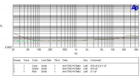
THD of caps
Here is a plot for comparing THD of a 470 uF e-cap with and without a 0.1 film cap in parallel. The THD of the film alone is also shown. The curves associated with the 470 uF e-cap do represent the residual distortion of my AP. It meas that no additional distortion can be measured for the e-cap.
Well, do we really need to parallel a film cap with the e-cap in NFB path. Yes, we can since it does nothing wrong objectively. It may make subjective differences. I don't know for sure. However, it does make some people feeling better who believe e-cap must be bypass by a film cap for better high-freq characteristic. This is true in certain applications, but not universal. Simply copy and paste does not engineering.
Last edited:
Even though picture quality is poor, there is a slight difference.
the film doesnt seem to handle lower frequencies too well, yet the electrolitic does a good job at "dampening" that. These 2 caps seem to compliment each other, where one makes up for the shortcoming of the other one.
the film doesnt seem to handle lower frequencies too well, yet the electrolitic does a good job at "dampening" that. These 2 caps seem to compliment each other, where one makes up for the shortcoming of the other one.
I probably have to make HD pictures.
The e-cap alone and in parallel with a film do not show any measurement difference. From the measured result, I can't see a reason to add a film cap.
The e-cap alone and in parallel with a film do not show any measurement difference. From the measured result, I can't see a reason to add a film cap.
to avoid using any e-cap in the NFB path, JLH used a pair of 4.7uF film caps in parallel and adjusted the NFB resistors up in value to bring back some bass response.
He did this even though the very high resistor values would increase amplifier noise slightly because he thought the sound quality improvement brought about by the no e-cap solution was a better compromise than reducing noise.
He did this even though the very high resistor values would increase amplifier noise slightly because he thought the sound quality improvement brought about by the no e-cap solution was a better compromise than reducing noise.
I probably have to make HD pictures.
The e-cap alone and in parallel with a film do not show any measurement difference. From the measured result, I can't see a reason to add a film cap.
I just came across this article, I haven't looked for these caps, don't know if they are available. The article mentions "very good frequency response" that these caps are better for decoupling than standard alum electros.
http://archive.chipcenter.com/eexpert/akruger/akruger007.html
but only for decoupling and particularly good for decoupling VHF. This is where they perform very well, in digital circuit with their very fast ON/OFF/ON/OFF going into the Gswitches/second....... The article mentions "very good frequency response" that these caps are better for decoupling than standard alum electros.
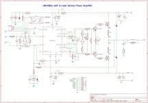
New board layout
I am working on a new layout for 3-lead power devices. KiCad is employed for the new board. Here is the schematic. Compared to the previous version, the following items are added.
Any comment is welcome.
I am working on a new layout for 3-lead power devices. KiCad is employed for the new board. Here is the schematic. Compared to the previous version, the following items are added.
- input DC blocking film cap
- 7.5 mm and 10 mm film cap footprints
- multiple footprints for NFB e-cap supporting ELAN SILMIC II
- 3.5 mm and 5 mm footprints for decoupling e-caps
- output coil and Zobel network
- separate rails for LME
Any comment is welcome.
Attachments
Last edited:
- Home
- Amplifiers
- Chip Amps
- Compact Sized LME49810/11 +ThermalTrak Amp