Thank you for all your valuable inputs.
I will most likely do the followings.
I have not decided for one or two pair output devices. The Compact board is aimed for output <= 60 W into 8 Ohms. This is expected for delivering large current into heavy loads.
I will most likely do the followings.
- Output coil and Zobel network
- Vbe multiplier with TT diodes
- Accommodate 3-lead TO-264 and TT power devices
- Driver shares the main heat sink
I have not decided for one or two pair output devices. The Compact board is aimed for output <= 60 W into 8 Ohms. This is expected for delivering large current into heavy loads.
Is there a disadvantage of using 2 pairs?
I am still using the compactamp I built in early 2010 and am quite happy with it. If a board would be designed by Panson I would happily be a "beta tester" for the new PCB's 🙂
I am still using the compactamp I built in early 2010 and am quite happy with it. If a board would be designed by Panson I would happily be a "beta tester" for the new PCB's 🙂
LME-AMP design
Hi panson,
for better understanding -
please could you explain why using driver-stage?
LME 49810/49830 offer plenty of drive current.......
Would be nice to go HIGHEND and give LME a proper powerregulation.
Regards Harry
Hi panson,
for better understanding -
please could you explain why using driver-stage?
LME 49810/49830 offer plenty of drive current.......
Would be nice to go HIGHEND and give LME a proper powerregulation.
Regards Harry
I would suggest that a one pair output stage for 60W into 8ohms is not a high current style amplifier.........I have not decided for one or two pair output devices. The Compact board is aimed for output <= 60 W into 8 Ohms. This is expected for delivering large current into heavy loads.
A two pair would qualify as high current.
The builders choose which they require.
A 3pr output stage gets into "stupendous" current performance if the whole amp is designed to meet that performance target.
Hi panson,
If you need not more than about 100W/8Ohm, then I prefer a circuit like audioman55 described in our forum:
>>LME49811(class A output) with one pair Sanken STD03N/P
regards Harry
Harry,
Can you provide a link to the aforementioned thread? I searched and didn't find any obvious reference.
Thanks,
Ken
Hi Panson,
I was in a bit of a rush last time I posted. You might remember that I had previously experimented with Bob Cordell's Thermaltrak VBE scheme that he published in the Thermaltrak thread. (I remember that you were also searching for tight tracking of the bias regardless of temperature.) With that configuration, I was not able to get completely accurate bias tracking. It was good, but, did not hold the bias at exactly the same level regardless of temperature. The bias increased slightly with temperature, say 10mV from 30degC to 50 deg C. I was able to make Bob aware of this, I believe that the schemes in his book might be better than the one he posted in the original thermaltrak thread.
Ken
Look here, it uses Vbe multiplier from Cordell's book:Harry,
Can you provide a link to the aforementioned thread? I searched and didn't find any obvious reference.
Thanks,
Ken
Hi Panson,
I was in a bit of a rush last time I posted. You might remember that I had previously experimented with Bob Cordell's Thermaltrak VBE scheme that he published in the Thermaltrak thread. (I remember that you were also searching for tight tracking of the bias regardless of temperature.) With that configuration, I was not able to get completely accurate bias tracking. It was good, but, did not hold the bias at exactly the same level regardless of temperature. The bias increased slightly with temperature, say 10mV from 30degC to 50 deg C. I was able to make Bob aware of this, I believe that the schemes in his book might be better than the one he posted in the original thermaltrak thread.
Ken
http://www.diyaudio.com/forums/solid-state/182554-thermaltrak-tmc-amp-3.html#post2751316
dado
Is there a disadvantage of using 2 pairs?
I am still using the compactamp I built in early 2010 and am quite happy with it. If a board would be designed by Panson I would happily be a "beta tester" for the new PCB's 🙂
Thank you for willing to be a beta tester. There is technical disadvantage for 2 pairs. For a low power design, two pairs may not be necessary.
Hi panson,
for better understanding -
please could you explain why using driver-stage?
LME 49810/49830 offer plenty of drive current.......
Would be nice to go HIGHEND and give LME a proper powerregulation.
Regards Harry
Hi Harry,
The driver is definitely needed for 49811 even in this Compact board. I prefer the LME regulator on another board.
Panson
Hi Panson,
I was in a bit of a rush last time I posted. You might remember that I had previously experimented with Bob Cordell's Thermaltrak VBE scheme that he published in the Thermaltrak thread. (I remember that you were also searching for tight tracking of the bias regardless of temperature.) With that configuration, I was not able to get completely accurate bias tracking. It was good, but, did not hold the bias at exactly the same level regardless of temperature. The bias increased slightly with temperature, say 10mV from 30degC to 50 deg C. I was able to make Bob aware of this, I believe that the schemes in his book might be better than the one he posted in the original thermaltrak thread.
Ken
Hi Ken,
I have Bob's book and considering to put this bias spreader in the new board.
Thanks.
Panson
High End with LME
Hi,
@klewis:
read thread "National OpAmp Inflation"
from page 15 to 23 audioman55 describes his preferences.
Additionally see AN 1490.
@panson:
I agree,
to get a simple routed pcb, wouldn't it be possible to get rid of the driver stage when using LME49810/49830? Both devices offer plenty of drive current for multi darlington outputstages.
Even LME49811 and two output pairs of STD03N/P darlingtons should be possible. STD devices offer 15A. An elegant solution !?
If you prefer LME49811 with non darlington outputstage, drivers are needed.
But if implementation isn't perfect, THD will rise.
🙂) yes, I like it simple !
Regards Harry
Hi,
@panson:
I agree,
to get a simple routed pcb, wouldn't it be possible to get rid of the driver stage when using LME49810/49830? Both devices offer plenty of drive current for multi darlington outputstages.
Even LME49811 and two output pairs of STD03N/P darlingtons should be possible. STD devices offer 15A. An elegant solution !?
If you prefer LME49811 with non darlington outputstage, drivers are needed.
But if implementation isn't perfect, THD will rise.
🙂) yes, I like it simple !
Regards Harry
Hi Harry,
I prefer ThermalTrak since it is more flexible for bias arrangement. STD got the diode connected to its base terminal which limits the flexibility.
For 49810/30, if driver is not wanted, we can simply short the corresponding B-E pads and not populate the driver emitter resistor.
To my experience with the LME498xx so far, I don't see any obstacle to get decent performance with external driver.
Cheers,
Panson
Last edited:
if you are designing for a mass market manufacturer then use a Darlington in lieu of a driver and rise to the reputation that the manufacturers of these cost costing devices fully deserve.wouldn't it be possible to get rid of the driver stage when using LME49810/49830? Both devices offer plenty of drive current for multi darlington outputstages.
If you prefer LME49811 with non darlington outputstage, drivers are needed.
But if implementation isn't perfect, THD will rise.
If you want to do it right, you must use a dedicated driver and a dedicated output device.
Try estimating the the current gain of combined driver and output where the designer has control of all the component values. Do this over a wide range of output currents, say10mA to 10,000mA.
Try doing a similar current gain prediction for an integrated Darlington using the Manufacturer's datasheet.
Integrated Darlington is penny pinching in exchange for quality of performance.
HighEnd LME
Hi,
thanks for responding my questions,
@panson
ok,I think you are right, but for me highend is regulated LME and drivers - so I would be happy 🙂))
May be your highend quad output amp has regulation on board?
@AndrewT
I agree, but going the way with drivers adds some more unwanted complexity.
For explanation : here we do DIY !
anybody is building his own stuff - very good in my opinion!
But outside there are "millions" of +/- identically circuits.... .
I don't want to add the next similar circuit to my HIFIcrap.
Therefore I don't join GB "The Wire Amp" by opc - also unregulated LME.
Means : if adding regulation to LME - you also had to add regulation to the drivers.
Who's building his own stuff - and is able to hear - needs not more than max.20s to prefer a circuit with regulated input circuit and (if build in) regulated drivers. I tried this several times.
Will say unregulated output stage is ok, all other power sucking crap had to be regulated - you might call this my "highend statement" 🙂
Engineers mostly may retort this will not spice... yes, may be,does not.
But they are all not able to hear, they are fixed on their superduper
measurements! For them hearing and comparing isn't worth while.
Not cost effective!
Other people are hearing with plastic dome tweeters and 17cm bass/mid speaker in bassreflex cabinet. Discussion about deepest bass lines or finest treble resolution is like to explain a blind man colours.
I tried this - without any results - on HighEnd-Exhibition in Munich..... what a funny experience - hahahahahaha ;-(((( highend - hahahahaha.
Regards Harry
my guess its you did not actually read even the first page of the thread properly, or just read enough to form prejudicial opinion and moved on.
'the wire' has regulated input stage set to 10v higher than outputs. before you go running your mouth its probably best to know what you are talking about. the (rather good) numbers on the initial amp prototype were unregulated, with single ended inputs and on breadboard but the idea is and has always been to run regulated psu for the front end, with the option to run unregulated if you want. we are also looking at the possibility of quality smps with regulated input AND output
'the wire' has regulated input stage set to 10v higher than outputs. before you go running your mouth its probably best to know what you are talking about. the (rather good) numbers on the initial amp prototype were unregulated, with single ended inputs and on breadboard but the idea is and has always been to run regulated psu for the front end, with the option to run unregulated if you want. we are also looking at the possibility of quality smps with regulated input AND output
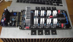
Keep us informed!This is my "Hi-End" LME. The power board (Triple, four pairs power devices) is a new layout. I will post its performance data.
Thank you guys.
I post the result of my "Hi-End" LME in http://www.diyaudio.com/forums/chip-amps/199132-my-hi-end-current-lme498xx-amplifier.html
I post the result of my "Hi-End" LME in http://www.diyaudio.com/forums/chip-amps/199132-my-hi-end-current-lme498xx-amplifier.html
regulated supply not regulated LME !!!
Hi,
@qusp
thank you for personal adressed "compliment".
Do you think this is gentlemen-like?
Anyway...........
I read "Wire Amp" thread carefully.
see post1 schematic : circuit is shown with 3 active elements = LME + 2xMosfets, nothing else.
Discussion runs about regulated supply, not about regulation on board with LME.
Do you think regulation far away from consumer LME, elswhere in the amp-case, is a good choice?
There is only one technical solution that fits for best regulation : minimum space to consumer(LME).
Regulated supplies may be good enough for pre-regulation,
do you see any regulation near by LME on pcb?
NO,.........no regulation on board.
Compliment back to sender
Regards Harry
Hi Panson,
first of all I'd like to thank you for your well documented and well engineered designs. That's quite a massive effort. I'm also impressed how good your PCBs look.
Perhaps there's still some room for improvements. When I took a look at roenders PCB layout for his RMI-FC100 amplifier, I thought, that the layout could hardly be done any better. I especially like the idea to incorporate some massive supply capacitors and some low esr capacitors right at the power devices. I'm not sure, if the local capacitors at the outputs should be grounded as in his layout or better be connected directly to supply capacitor GND, but i'm no expert in grounding. Anyways, I think two big cans somewhere around 4,7-10mF and two 1000uF caps at the outputs could be a nice upgrade to your LME-Amp. Please consider this just as a remark on your highly appreciated work.
Thank you.
- Home
- Amplifiers
- Chip Amps
- Compact Sized LME49810/11 +ThermalTrak Amp