Hi Juma,
This is the point, though. Everything is the same *now*, because I found the difference between the trimpots on left and right and adjusted it, but when I replaced the mosfet (for the second time) the trimpots were not at the same value - the one on the right hand channel was about 70k, the one on the left about 45k. (I can't remember the exact numbers now). This is the only difference between channels I could find. Although I can't see what difference it would make, it *is* directly linked to the mosfet that blew.....
Cheers, and thx
Nigel
It seems that you have the same standing current, same heatsinks and same temperature on both channels, so everything being the same ....
This is the point, though. Everything is the same *now*, because I found the difference between the trimpots on left and right and adjusted it, but when I replaced the mosfet (for the second time) the trimpots were not at the same value - the one on the right hand channel was about 70k, the one on the left about 45k. (I can't remember the exact numbers now). This is the only difference between channels I could find. Although I can't see what difference it would make, it *is* directly linked to the mosfet that blew.....
Cheers, and thx
Nigel
... Everything is the same *now*...
Keep it that way and hope for the best 😀
Cheers!
Keep it that way and hope for the best 😀
Cheers!
Well, hoping for the best didn't work... I've just been testing a diy DAC I was fiddling with, and the right channel on the amp has blown *again*... about 15VDC on the output, so the relay on the speaker protection circuit won't close, of course. I haven't checked the mosfet yet, but there can be little doubt it's the same thing again, since all the symptoms are the same.
I could really use some help here. There is no way that I've been unlucky three times with bad mosfets in that exact position; there must be *something* about my build that is wrong. I've checked for things like bad solder joints, or burned parts, and I can't find anything. I can only guess that it is something about the speaker protection circuit itself that is causing this. After turning the amp on there is a delay of about 3 to 5 secs before the relay trips; is it possible that this is stressing the mosfets somehow? Any asymmetry between the two channels might cause the same one to always fail first, if this is the case, although i really can't see how it could be so.
The schematic I used is the one from Rod Elliott's ESP site, and is the same one I used in my F5, where it has given no trouble at all. (Although admittedly I use it less often.) The relays I am using are big ones that slot into 8-pin tube sockets, and are biger than really necessary, but I can't see what difference that would make...
Any ideas or hints for where to look? I can't keep switching out the same mosfet every month or two..
Thanks for any help
Nigel
Vgs for both power FETs would be neat to know too, if things aren't getting hot too fast for you to get it.
Hi Nigel,
last time you did a thorough check on temperature of MOSFETs and it was fine. The only other thing capable of killing a MOSFET is too large a Vgs - in this case as the consequence of too large a current through R15 (which I believe is a trim-pot in your amp). Culprit can be Q8 - change it and check the surrounding resistors too.
Also, a bad R15 pot could cause an instantenious peak on the gate of Q6 (the ever dying MOSFET).
You could put a pair of protective zeners accross the R15 (9V1, anti-serialy connected) - that prevents excessive Vgs.
It's not unusual that components measure fine when cold and create problems when hot (so called "female behavior")... 😉
Last edited:
Hi Guys,
No-one has remarked on the protection circuit, so can I assume no-one thinks it's the culprit?
I'll try and measure some stuff later or tomorrow.
Changing Q8 is a piece of cake - it's in a little socket. I've been wondering about R15 also, so maybe I should replace it with a fixed resistor.
Now, since I posted last night I have been wondering whether something about the testing I was doing killed it. To plug/unplug the DAC would have meant switching the amp off, and then on again relatively quickly. If C1 or C3 were still charged could that have caused some kind of instantaneous peak?
By "anti-serially" you mean anode-to anode or cathode-to-cathode, right?
Well, thanks for the help.
Cheers
Nigel
No-one has remarked on the protection circuit, so can I assume no-one thinks it's the culprit?
What is the output drain current in the failed amplifier, and what is normal idle current?
Vgs for both power FETs would be neat to know too, if things aren't getting hot too fast for you to get it.
I'll try and measure some stuff later or tomorrow.
Hi Nigel,
last time you did a thorough check on temperature of MOSFETs and it was fine. The only other thing capable of killing a MOSFET is too large a Vgs - in this case as the consequence of too large a current through R15 (which I believe is a trim-pot in your amp). Culprit can be Q8 - change it and check the surrounding resistors too.
Changing Q8 is a piece of cake - it's in a little socket. I've been wondering about R15 also, so maybe I should replace it with a fixed resistor.
Also, a bad R15 pot could cause an instantenious peak on the gate of Q6 (the ever dying MOSFET).
Now, since I posted last night I have been wondering whether something about the testing I was doing killed it. To plug/unplug the DAC would have meant switching the amp off, and then on again relatively quickly. If C1 or C3 were still charged could that have caused some kind of instantaneous peak?
You could put a pair of protective zeners accross the R15 (9V1, anti-serialy connected) - that prevents excessive Vgs.
It's not unusual that components measure fine when cold and create problems when hot (so called "female behavior")... 😉
By "anti-serially" you mean anode-to anode or cathode-to-cathode, right?
Well, thanks for the help.
Cheers
Nigel
Good home amps don't need protection circuits - bad users do. Handle your amp properly and you dont need the protection. I don't know which circuit you use for this purpose but they often create more problems than they are solving. Try to get rid of it. If it's the turn-on thump that worries you - it shouldn't, 'cause kick of a drum at 5W is by far nastier transient yet amp and speaker cope with it effortlessly...No-one has remarked on the protection circuit, so can I assume no-one thinks it's the culprit?
The socket might ba a part of the problem - bad contact will shut the Q8 off and all the current will go through R15 (which you should make into fixed resistor if you are not sure about quality of the pot you have).Changing Q8 is a piece of cake - it's in a little socket. I've been wondering about R15 also, so maybe I should replace it with a fixed resistor.
No - caps always discharge through "shortest" path (least resistance).If C1 or C3 were still charged could that have caused some kind of instantaneous peak?
RightBy "anti-serially" you mean anode-to anode or cathode-to-cathode, right?
Juma, are you certain the turn-on thump is so minor? I would get those zeners in there right away. I was thinking maybe there was some reason they were purposefully omitted, although I think it's been shown that there isn't really. They will keep from crunching the gate, but I'd look at possible sizing of reference and divider filter caps so that the current sources rise and fall at a closer to equal rate. If you can do that maybe a de-thump relay will be needless extra. Also, if R12 is really a pot it would be better to wire the wiper in parallel with the element or use a parallel fixed resistor.
Knowing those voltages and currents would help to determine exactly what state the output stage is in and maybe how it got there.
Knowing those voltages and currents would help to determine exactly what state the output stage is in and maybe how it got there.
Last edited:
Hi Nigel,
I’m new to the diyAudio form but I have had more than 40 years experience building SS amps.
I have a few questions and a few comments,
1st Is the Q6 MOSFET really burnt? There are ways to test it such as the little matching circuit shown earlier.
2nd Is there really some reason why you are matching your power FETs? I far as I know you only have to match them if they are connected in parallel; your FETS are used in a Quasi-complementary output circuit with only one FET per side. Matching should not be required unless the gate’s on voltage is critical to the bias of the driving circuit, which I don’t believe is the case here.
3rd If the FET really is dead, than more than likely it was fried by a voltage surge being too large on the gate. This voltage surge could actually occur when you get your turn-off thump that seems to be plaguing your design. It’s possible that your amp actually died when you last turned it off. I would suggest that you put a 12v gate protection zener across the source and gate of each power FETs. The fact that its always Q6 blowing seems to point to this as the main cause to you problem.
4th The DC offset voltage variations are due to temperature differences between Q2 and Q5 (the differential pair) and this is due to uneven tail currents flowing through each device. At one time we use to put the LTP into direct physical contact with each other so that the temperature differences were kept to a minimum, but this was a Band-Aid fix for an improper design, and now by using SMD devices this is all but impossible. Using FETs for the LTP is not the best method for having a low output offset, a transistor pair would have been better in this regard. You may find that adding a new resistor (equal to R1) to the Drain of Q5 could help to minimize the effect. Better yet would be to incorporate a Cascade current mirror circuit as was suggested earlier. This would try to keep the current balanced in the LTP while at the same time lowering the PD on these sensitive devices and with a lower PD comes lower temperature drift thus further reducing the offset drift.
5th Another potential cause of the blowing the power FET could be that your forward BIAS circuit is not functioning properly (especially during turn on and off). I have read somewhere in an earlier thread where someone suggested changing R15 with a POT to adjust the forward bias, I don’t know if you did this but this would be wrong as any POT generated noise could turn-off Q8 resulting in the instant destruction of the output stage. If you want to adjust the bias it would be better to replace R22 with a 1k pot in series with a 680 ohm resistor.
6th To test if the blown transistor is caused by a bias fault, I would suggest that you measure the voltage across C1 (on the good channel) and construct a temporary diode series circuit (several 1n4001 rectifiers in series) whereby the total sum of all the diodes forward voltages comes out to a slightly higher value than the voltage across C1 assuming .65 volts per diode, and connect this series diode string across C1. Then try running your amp to see if if again blows the FET. Now if the bias circuit should open the diodes will clamp the voltage at a higher (but still safe level) and if you are diligent you should notice that the output FETS are getting warmer that usual
7th Another thing that might help would be to put a small fuse in the negative V1 supply hoping that the fuse will open before the FET fails.
Good luck with your design, I hope this may give you some useful clues.
Philip
In 27 years of my fiddlin' with audio I've never seen a speaker damaged by turn-on/off thump. It is unpleaseant but nothing more than that - calculate for your self how much power carries a 5V surge accross an 8 ohm speaker (and let me tell you that 5V surge sounds like the thunder strike)?Juma, are you certain the turn-on thump is so minor?
For properly executed circuit of this amp they are not needed (Nilgel's trouble is restricted to just one channel of his amp).I would get those zeners in there right away. I was thinking maybe there was some reason they were purposefully omitted....
Last edited:
I'm not worried about damaging a speaker with this amp. I'd just like to figure out why one of them is eating transistors, maybe by having them survive long enough to have that happen. It would neat to have the current sources rise in an innocuous way if it can be managed.
Last edited:
Nigel will tell us that (when he thoroughly inspects his amp, checks all the parts and the way he used them and compares the results with a properly working channel) 😉... I'd just like to figure out why one of them is eating transistors...
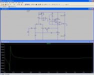
I ran a sim on this circuit showing application and removal of supplies. I used a .5ms supply rise and 1s fall.
The two plots are with 300u and 22u bypassing the reference diode. I only had a green diode to slap in, so some values might be slightly different. However, changing the bypass from 270 to 330 really throws it, with + or - peaks going up to 1 volt instead of les than .5. You can see that the transient last for a much shorter period, leaving a total of much less energy under the wave.
V(n012) is the output.
Turn off character is essentially unchanged.
Attachments


I realize .5ms is a little fast. With 100ms supply rise time 440uF is best. The transient is then again 100ms long but only 450mV P-P.
Alright. Somehow when changing the supply rise time to 100ms I dropped the supply to +/-14 volts.
With the supplies back at 18 volts the better seeming value for the diode filter total was 340uF. Turn on character for 100ms rise time attached.
The 22u value causes a 2.5V, 100ms square pulse instead. Turn off is still same.
With the supplies back at 18 volts the better seeming value for the diode filter total was 340uF. Turn on character for 100ms rise time attached.
The 22u value causes a 2.5V, 100ms square pulse instead. Turn off is still same.
Attachments
IRFP9240 shows 10db lower 2nd, 3db lower 3rd, and 3db lower 5th harmonic compared to the 12P20.
I'd run other transistors or post FFTs if anyone's interested.
I'd run other transistors or post FFTs if anyone's interested.
Hi Guys,
Wow, a lot to absorb in those replies... I'm not going to be able to work on this until the weekend, but I'm trying to think things through a bit. Andrew's posts may take a little time and brainpower to understand properly, but hopefully I'll get there. Meanwhile, let me reply to some of the posts.
The circuit I'm using is from Rod Elliott's site (project 33) which seems a widely tried and tested circuit. (Although it's not a pcb, just a p2p version). I'm not using it because of the turn on/off thump, since I think your logic is convincing on that score, but because another of my amps took out one of my speakers (FE127e) when it blew a mosfet. OK, so it was perhaps due to the failings of my build that the mosfet blew, but nonetheless these things happen. If you can see something about my *use* of the amp that might have caused the mosfet to blow it would help if you could be specific - my suspicion is that it is something about my *build* of the amp that caused it. I'm also a little resistant to removing the protection circuit since unless I put caps on the output my speakers are very vulnerable, and caps seem a worse idea...
I don't think the socket is likely to be the problem - I have used them in loads of places and they seem a nice tight fit. I wouldn't rule out the *soldering* of the socket without checking again, however 😉 I'm definitely going to get rid of the trimpot, in any case, since it was originally put in to help with DC offset, and in practice it hasn't helped with that.
Hi Philip, I'm sure the mosfet is dead, even though I haven't checked it yet, since the other two times this happened it was dead, and the symptoms (DC offset, current across power resistors et cetera) are exactly the same this time. In fact, simply putting a new one in put things straight both times.
There's maybe a little confusion here. I'm not matching the mosfets as such, just using the matching circuit to test for dead mosfets.
Last time this happened juma helped me look things over, and having ruled out problems with heatsinking last time I also think its a problem with some kind of voltage surge. (I think juma said he agrees, somewhere above.)
Your suggestion of a protection zener seems similar to the idea of anode-to-anode zeners he proposed above, right?
I'll have to read through your 4th with more care later...
Now, some version of what you describe is what I suspect is the problem, although I can't rule out the protection circuit having a hand in the process...
That's an interesting idea, although it'll have to wait until I get a new mosfet in on the weekend....
Actually I have fuses in both rails, but the mosfet blew before they did. I can't remember what value they are without looking - probably 2A or perhaps 3A. I really intended them for *my* protection in case of catastrophic PSU failure, not the amps protection....
May thanks for the help, although let me point out that it's juma's design, not mine, and in my opinion a very good one. It sounds very good when working properly, and any flaws are doubtless my building errors, not his design.
I think I said above I'm not really worried about the on/off thump, but I *am* worried about blowing my speakers with a huge DC offset due to a blown mosfet. Do I have any alternative except output caps?
Hmmmm.... I'll gladly accept the criticism, since evidently there is something wrong with my build ....😱 It would be nice to really understand what's wrong, though... I guess I'll get there with a little help...
I certainly will. Here's my list (so far) of things to do.
1. Get rid of the trimpots, replace with 47k fixed resistors. Check all other parts around Q6, especially Q8.
2. Replace the dead mosfet.
3. Measure Vgs and bias current in stable state, and try to measure if there is a surge when turning on/off.
4. Report back here before putting zeners or other parts in. 😀
Anything else I should put in this (first) list?
OK, many thanks for the help, and I hope people won't let my troubles with the amp put them off trying juma's schematic - it really does sound great when working properly.
Cheers
Nigel
Wow, a lot to absorb in those replies... I'm not going to be able to work on this until the weekend, but I'm trying to think things through a bit. Andrew's posts may take a little time and brainpower to understand properly, but hopefully I'll get there. Meanwhile, let me reply to some of the posts.
Good home amps don't need protection circuits - bad users do. Handle your amp properly and you dont need the protection. I don't know which circuit you use for this purpose but they often create more problems than they are solving. Try to get rid of it. If it's the turn-on thump that worries you - it shouldn't, 'cause kick of a drum at 5W is by far nastier transient yet amp and speaker cope with it effortlessly...
The circuit I'm using is from Rod Elliott's site (project 33) which seems a widely tried and tested circuit. (Although it's not a pcb, just a p2p version). I'm not using it because of the turn on/off thump, since I think your logic is convincing on that score, but because another of my amps took out one of my speakers (FE127e) when it blew a mosfet. OK, so it was perhaps due to the failings of my build that the mosfet blew, but nonetheless these things happen. If you can see something about my *use* of the amp that might have caused the mosfet to blow it would help if you could be specific - my suspicion is that it is something about my *build* of the amp that caused it. I'm also a little resistant to removing the protection circuit since unless I put caps on the output my speakers are very vulnerable, and caps seem a worse idea...
The socket might ba a part of the problem - bad contact will shut the Q8 off and all the current will go through R15 (which you should make into fixed resistor if you are not sure about quality of the pot you have).
I don't think the socket is likely to be the problem - I have used them in loads of places and they seem a nice tight fit. I wouldn't rule out the *soldering* of the socket without checking again, however 😉 I'm definitely going to get rid of the trimpot, in any case, since it was originally put in to help with DC offset, and in practice it hasn't helped with that.
Hi Nigel,
I’m new to the diyAudio form but I have had more than 40 years experience building SS amps.
I have a few questions and a few comments,
1st Is the Q6 MOSFET really burnt? There are ways to test it such as the little matching circuit shown earlier.
Hi Philip, I'm sure the mosfet is dead, even though I haven't checked it yet, since the other two times this happened it was dead, and the symptoms (DC offset, current across power resistors et cetera) are exactly the same this time. In fact, simply putting a new one in put things straight both times.
2nd Is there really some reason why you are matching your power FETs? I far as I know you only have to match them if they are connected in parallel; your FETS are used in a Quasi-complementary output circuit with only one FET per side. Matching should not be required unless the gate’s on voltage is critical to the bias of the driving circuit, which I don’t believe is the case here.
There's maybe a little confusion here. I'm not matching the mosfets as such, just using the matching circuit to test for dead mosfets.
3rd If the FET really is dead, than more than likely it was fried by a voltage surge being too large on the gate. This voltage surge could actually occur when you get your turn-off thump that seems to be plaguing your design. It’s possible that your amp actually died when you last turned it off. I would suggest that you put a 12v gate protection zener across the source and gate of each power FETs. The fact that its always Q6 blowing seems to point to this as the main cause to you problem.
Last time this happened juma helped me look things over, and having ruled out problems with heatsinking last time I also think its a problem with some kind of voltage surge. (I think juma said he agrees, somewhere above.)
Your suggestion of a protection zener seems similar to the idea of anode-to-anode zeners he proposed above, right?
I'll have to read through your 4th with more care later...
5th Another potential cause of the blowing the power FET could be that your forward BIAS circuit is not functioning properly (especially during turn on and off). I have read somewhere in an earlier thread where someone suggested changing R15 with a POT to adjust the forward bias, I don’t know if you did this but this would be wrong as any POT generated noise could turn-off Q8 resulting in the instant destruction of the output stage. If you want to adjust the bias it would be better to replace R22 with a 1k pot in series with a 680 ohm resistor.
Now, some version of what you describe is what I suspect is the problem, although I can't rule out the protection circuit having a hand in the process...
6th To test if the blown transistor is caused by a bias fault, I would suggest that you measure the voltage across C1 (on the good channel) and construct a temporary diode series circuit (several 1n4001 rectifiers in series) whereby the total sum of all the diodes forward voltages comes out to a slightly higher value than the voltage across C1 assuming .65 volts per diode, and connect this series diode string across C1. Then try running your amp to see if if again blows the FET. Now if the bias circuit should open the diodes will clamp the voltage at a higher (but still safe level) and if you are diligent you should notice that the output FETS are getting warmer that usual
That's an interesting idea, although it'll have to wait until I get a new mosfet in on the weekend....
7th Another thing that might help would be to put a small fuse in the negative V1 supply hoping that the fuse will open before the FET fails.
Actually I have fuses in both rails, but the mosfet blew before they did. I can't remember what value they are without looking - probably 2A or perhaps 3A. I really intended them for *my* protection in case of catastrophic PSU failure, not the amps protection....
Good luck with your design, I hope this may give you some useful clues.
May thanks for the help, although let me point out that it's juma's design, not mine, and in my opinion a very good one. It sounds very good when working properly, and any flaws are doubtless my building errors, not his design.
In 27 years of my fiddlin' with audio I've never seen a speaker damaged by turn-on/off thump. It is unpleaseant but nothing more than that - calculate for your self how much power carries a 5V surge accross an 8 ohm speaker (and let me tell you that 5V surge sounds like the thunder strike)?
I think I said above I'm not really worried about the on/off thump, but I *am* worried about blowing my speakers with a huge DC offset due to a blown mosfet. Do I have any alternative except output caps?
For properly executed circuit of this amp they are not needed (Nilgel's trouble is restricted to just one channel of his amp).
Hmmmm.... I'll gladly accept the criticism, since evidently there is something wrong with my build ....😱 It would be nice to really understand what's wrong, though... I guess I'll get there with a little help...
Nigel will tell us that (when he thoroughly inspects his amp, checks all the parts and the way he used them and compares the results with a properly working channel) 😉
I certainly will. Here's my list (so far) of things to do.
1. Get rid of the trimpots, replace with 47k fixed resistors. Check all other parts around Q6, especially Q8.
2. Replace the dead mosfet.
3. Measure Vgs and bias current in stable state, and try to measure if there is a surge when turning on/off.
4. Report back here before putting zeners or other parts in. 😀
Anything else I should put in this (first) list?
OK, many thanks for the help, and I hope people won't let my troubles with the amp put them off trying juma's schematic - it really does sound great when working properly.
Cheers
Nigel
.... it really does sound great when working properly.
....
It works properly for sure, but it needs to be made properly. Otherwise you'd have the some problem on both channels. Concentrate on differences between the channels - yes, it's a lot of work, but you can't avoid it if you want to really sort the things out.... 😱
Hi Guys,
So here's a progress report. I spent most of the day fiddling around with the amplifier to try and find out what's wrong, and so far have only managed to confuse myself. Here's what I've found so far.
Before taking anything apart I tried to measure as much as I could to see what is different between the left channel (working) and the right (not working).
1. I found 0.581V and 0.586V across the resistors R7 and R16 on the left channel, which means a bias current of just over 1A, which is about right, but on the right channel only 0.012V on R7 and 0.0 on R16, which is obviously wrong, and means the Aleph current source is not working. (Right??)
2. Vgs on the left channel was 4.11V on Q6 and 4.10V on Q3, which is just fine, but on the right channel was 3.46 on Q6 and 9.67 (!!) on Q3. Again, definitely far from OK.
3. R1 (the drain resistor on the LTP) showed 4.67V on the left channel, and voltages across R10 and R11 were close to equal, as they should be if current throught the matched pair of BF862s is to be the same, but on the right channel R1 showed 9.63V, and R11 showed 0V, so the LTP wasn't working correctly.
So I then decided to match a new pair of BF862s and replace the LTP, to eliminate that as a factor. Took a little time, but made no real difference.
I then replaced the trimpot R15 with a fixed resistor (initially 67k, later switched to 47k, but the value shouldn't be the real issue, right?), put new mosfets in for Q6 and Q3, new BC557 in for Q8... (I also put the back-to-back zeners across R15, which had a voltage of 9.65 across them, so they were working, but it means the voltage across R15 was too high, right? I have taken them back out for the time being...)
...and nothing made any difference. Or rather, I *did* get voltages across R7 and R16, but never the same ones, or the same as on the left channel. Right now they both show zero again.
Now, when they showed zero I presumed that I had burned Q6 again, but it seemed prudent to check the ones I had taken off, and (surprise!) they both show Vgs of about 3.9V (using the test circuit juma posted above) so they are OK, right? This leads me to suspect that they weren't the problem before either... however just replacing them had fixed the amp without doing anything else at all, so I am most confused... 😕 (Philip: apparently you were right to query this...)
I am also at a loss as to what to do next. The problem must be an error in my construction of the board, but I can't find what is wrong. Also, I have now switched out components on this board so may times that it is in a poor state, and I am considering rebuilding this channel completely. If I do this then I would change things a bit, since I can see ways to improve the construction now, but if I do it all again I will *never* know what the problem was, which is a bit frustrating...
Well, if anyone has any suggestions I'd be glad to hear them. I'm also pretty tired now, so I hope the post makes sense.
Cheers, and thanks
Nigel
- Status
- Not open for further replies.
- Home
- Amplifiers
- Pass Labs
- Is a mini-Aleph using BF862 possible?