I measured and I have a 26V output.
What I have to change for 24V?.
I've tested with no load (with multimeter) and within seconds Q4 gets very very hot, and that having a sink.
Hi albertob!
you you need V-out 26V, so V-in = 36V (About vin to v-out 10V it is ok for ripper)
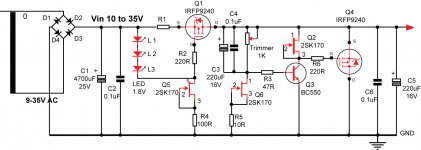
If you need change V-out you need change zenner diode by one trimmer 1K!
What I have to change for 24V?.
I've tested with no load (with multimeter) and within seconds Q4 gets very very hot, and that having a sink.
Hi albertob!
you you need V-out 26V, so V-in = 36V (About vin to v-out 10V it is ok for ripper)
If you need change V-out you need change zenner diode by one trimmer 1K!
Do I have to change R6 (1k) to vary the output voltage?
No, that's for better performance changing to a fet. Will work as is it is with 1k now too. You will change the Zener to a resistor or 5k trimmer.
Do I have to change R6 (1k) to vary the output voltage?
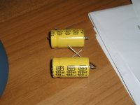
this image can help you!
Attachments
Last edited:
Do I have to change R6 (1k) to vary the output voltage?
@albertob
Really nice to hear something writing from Spain like me, go follows Salas advice & enter to Salas shunt dimension
 & let us know sending your photos & subjective opinion.
@Salas
hiFace entered V1.0 RS shunt dimension +5V, now I try separate regulation for clocks, togheter Erno Borbely I/V hirez digital records sounds very close to Salas phono RIAA, when change 16nF RIAA cap possible perform better in highs the phono.
hiFace entered V1.0 RS shunt dimension +5V, now I try separate regulation for clocks, togheter Erno Borbely I/V hirez digital records sounds very close to Salas phono RIAA, when change 16nF RIAA cap possible perform better in highs the phono.
Hi everybody
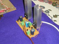
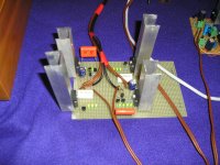
This is my opamp phono stage that I’ll try to feed with shunt reg.
Now is operated by lm317 / 7818
I’ll tell you the differences when is finished.
(Thanks Salas)
Hi folks
I asked Salas for three circuits of regs in order to supply my phono stage; so he gave me the follow diagrams (Thanks Salas). The first two are for the step up that needs +-9V, the last for the main phono +18V.
I made +-9V last week and was used a previous version for the 18Vhttp://www.diyaudio.com/forums/power...ml#post2106695
There is big difference from the old Lm317/78xx. I have to describe when is finished.
I have some questions about the drawings:
1. In order to keep the size of regs as small as possible could I use a litic cap for C1 (4.7uF MKP), without lose of quality? What capacity? I’ve put a cheep orange 4.7uf MKT for the time.
2. Does C2 (100uF) enough? I ask because the original diagram of my phono has (2X470uF + 10uF tant) per side after 78XX, 79XX.
3. What is the max length of cable that I can use for supply and sense?
Attachments


Last edited:
Hi, nice progress.
1. For the +/-9V with LEDs 4u7 is OK, keep it MKT or better MKP. For the +18V, due to the rather small Rref, 15uF at least is needed so to keep the closed loop gain strong down to very low frequencies. C1's quality is influential subjectively. One idea to keep it compact and cheap would be two 100uF non polar in series, to make a 50uF non polar instead of a 15uF film. Series non polar was the least THD lytic cap in Bateman's tests for Electronics World, far lower than BG and Silmic. Your now 18V is the same thing I see. Why make it again? Just use the non polars & Q2 2SK on it.
2. C2 does not do what it does in the chip regs. Follow the given values.
3. As long as you like. Sense is there exactly to counteract that. Now if there will be any adversities with cable characteristics and sense wiring it will surely show. If it will oscillate it will buzz on phono's signal.🙂 If you have an oscilloscope check your B+ lines in the end when working on real load, to make sure they are a straight thin line (I.e. DC with no noise or oscillations).
Is that a Japanese DD turntable?
Hi, nice progress.
1. For the +/-9V with LEDs 4u7 is OK, keep it MKT or better MKP. For the +18V, due to the rather small Rref, 15uF at least is needed so to keep the closed loop gain strong down to very low frequencies. C1's quality is influential subjectively. One idea to keep it compact and cheap would be two 100uF non polar in series, to make a 50uF non polar instead of a 15uF film. Series non polar was the least THD lytic cap in Bateman's tests for Electronics World, far lower than BG and Silmic. Your now 18V is the same thing I see. Why make it again? Just use the non polars & Q2 2SK on it.
2. C2 does not do what it does in the chip regs. Follow the given values.
3. As long as you like. Sense is there exactly to counteract that. Now if there will be any adversities with cable characteristics and sense wiring it will surely show. If it will oscillate it will buzz on phono's signal.🙂 If you have an oscilloscope check your B+ lines in the end when working on real load, to make sure they are a straight thin line (I.e. DC with no noise or oscillations).
Is that a Japanese DD turntable?
1. Now I use BF245A for Q2. Do I have to change it?
2. No comments
3. I like this, because I have 1.2m power cables
It’s not as good as direct drive Japanese turntable, but it’s nice.🙂
BF245A is there in the 45V schematic because a 2SK170 would heat up the BJT underneath a lot at such a voltage scale. But in your 18V case the higher IDSS of the Toshiba will be useful for having more current to drive the Mosfet. The ring of two BJT LEDs constant current sink is good since your Vinput is high, has more max than a Jfet.
What is your TT and cart?
What is your TT and cart?
BF245A is there in the 45V schematic because a 2SK170 would heat up the BJT underneath a lot at such a voltage scale. But in your 18V case the higher IDSS of the Toshiba will be useful for having more current to drive the Mosfet. The ring of two BJT LEDs constant current sink is good since your Vinput is high, has more max than a Jfet.
What is your TT and cart?
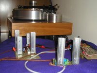
So in my case I have to make the third diagram for 18V. Isn’t it?
The TT is an Acoustic Solid -Wood- with RB300 and Shelter 501
Acoustic Solid
You can hear it if you like!
Attachments
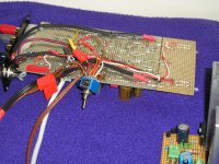
Today I bought two non polar capacitors and I am going to change the C2 100uf lytic. I have to change Q2 from BF245A to 2SK170BL (IDSS 6.84). Do I change the Q3 from BC 546B to BC550C or not? Also may I keep the Q1,Q4 IRFP9140 or change to IRFP9240? I have got both.
Don't forget. The Vin is 30V and the Vout 18V
Don't forget. The Vin is 30V and the Vout 18V
Attachments
Last edited:
Don't change the IRFP, what you got is equivalent or slightly better even.
Put 550C too, here your voltage will not challenge it and has more hfe and better noise. Thought you had 41V in, did you drop it with RC prefeltering?
Put 550C too, here your voltage will not challenge it and has more hfe and better noise. Thought you had 41V in, did you drop it with RC prefeltering?
Yes I will do it.Thought you had 41V in, did you drop it with RC prefeltering?
It plays very-very good as it is!!! Now I am hearing
Last edited:
Tell us if you can pick up the back to back non polars change later with the rest of chip regs vs new regs evaluation info. Maybe its a mid way good solution to do well enough without the bulk and cost of MKP bypassing.
Cap Vref question?
Can I use 100uF/450VDC pp metallized Solen instead the lytic 1000uF Vref cap for Shunt TT DC motor, Disco reg 1.5V & for V1.0 RS?
I have 8 caps without use & several are news.
Or will be better two BG non polar caps 100uF/50V in series?
I have 6 caps without use.
Can I use 100uF/450VDC pp metallized Solen instead the lytic 1000uF Vref cap for Shunt TT DC motor, Disco reg 1.5V & for V1.0 RS?
An externally hosted image should be here but it was not working when we last tested it.
I have 8 caps without use & several are news.
Or will be better two BG non polar caps 100uF/50V in series?
An externally hosted image should be here but it was not working when we last tested it.
I have 6 caps without use.
Last edited:
If you have enough space, use 100uF/450V MKP Solen.
Two BG 100uF connected in series will give you 50uF and connected in parallel will give you 200uF.
PS: Are those 100uF Solen caps motor start-up and run capacitors?
Two BG 100uF connected in series will give you 50uF and connected in parallel will give you 200uF.
PS: Are those 100uF Solen caps motor start-up and run capacitors?
Last edited:
- Status
- Not open for further replies.
- Home
- Amplifiers
- Power Supplies
- The simplistic Salas low voltage shunt regulator