Please, not in this Thread.Then we can discuss burn in of semiconductors, film capacitors, resistors or even wires. Here is where you will hear the funniest arguments.
I will be asking the Moderators to remove any Off Topic posts that go in that direction.
What does that mean?(no only BG)
you can re-form the black gate 220uF while in circuit, if both ICs are not in place.
There will be a small current flowing around R7, R8, R9, R10, dissipation of these <40mW @ 50Vdc reforming voltage and zero series reforming resistor.
There will be a small current flowing around R7, R8, R9, R10, dissipation of these <40mW @ 50Vdc reforming voltage and zero series reforming resistor.
Was I intended to start a talk about that? I just was resuming for him the measurable facts given by the manufacturers. Each one must then try and have his own opinion.Please, not in this Thread.
I will be asking the Moderators to remove any Off Topic posts that go in that direction.
Is this the build thread as well?
I might have a start at plopping a few resistors in tomorrow!
I might have a start at plopping a few resistors in tomorrow!
no, there is a separate build thread.Is this the build thread as well?
This Thread is more for the design basis of MyRefC
Package delivered. all parts looks great.
Thank You, Uriah. It's a great inspiring feeling to dive into the project
Vladimir
Thank You, Uriah. It's a great inspiring feeling to dive into the project
Vladimir
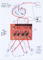
Here is one way
I received this drawing from Jon,
Uriah's way has a balance control and Volume control.
Dual pot is volume, single 5k pot is balance, courtesy of Uriah.
Is there another builder from the GB that has assembled its LDR volume?
I received this drawing from Jon,
Uriah's way has a balance control and Volume control.
Dual pot is volume, single 5k pot is balance, courtesy of Uriah.
Attachments
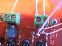
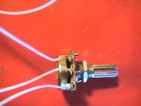
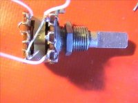
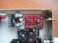
I have seen that drawing and its correct. The dual pot is 100k linear. This will get you going til you buy a dual 100k log. I threw in the linear's for free as I had a bunch of them from Allelectronics, bought on accident and while they will work fine there will be a quick volume increase. The single gang is a 5k. The wiper, middle pin, of the 5k goes to the middle pin hole of the series balance pads on the small LDR board.
Uriah
EDIT Some people like to connect signal ground to power ground. This is not a real good idea in my opinion. Keep them separate.
Also, I would echo PJN's comments about sound. Its a nice amp. Hope to hear from more of you as to how you like the sound.
Uriah
EDIT Some people like to connect signal ground to power ground. This is not a real good idea in my opinion. Keep them separate.
Also, I would echo PJN's comments about sound. Its a nice amp. Hope to hear from more of you as to how you like the sound.
Last edited:
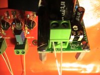
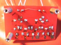
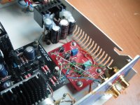
I should mention that in those pics PPCBLASTER posted that power ground is connected under the board. The two terminal block areas each have a + and - area. Just short the two "-" together as sharing ground is fine for the two power areas. Then you only need one wire to the ground on your power supply. Ground in this case is actually just 0V.
I should mention that in those pics PPCBLASTER posted that power ground is connected under the board. The two terminal block areas each have a + and - area. Just short the two "-" together as sharing ground is fine for the two power areas. Then you only need one wire to the ground on your power supply. Ground in this case is actually just 0V.
"power ground is connected under the board"
Attachments
Hi Uriah -
A couple of questions about the '5k balance' pot. Should we go to the trouble of getting a pot with a 'detent' in the middle-if so wouldn't other adjustments be needed to 'center' it; or, is the balance just a way to fine tune the R/L levels??? And, am I correct in assuming that the 'outer' two pins of the '5k balance' pot can go to either other pin on the p1 pad???
BTW - 'a perfect timing badge' to ppcblaster: I'm hoping to get my 'MyRevC' working this weekend (at least on a board - case work will take a while).
Thanks,
Last edited:
No, any old 5k pot will work. There is 1k on either side because of the resistors so you cant use to small of a pot and log or linear. I suggest tuning the center by ear rather than by a center detent or multimeter. When you sit in your favorite spot you want the image in front of you and your gear or room may change the center of the image to the right or left of that spot so just do it by ear, which means we dont care anything about the pot. Even a 2k5 or 3k or 4k pot would be fine if you have something other than 5k. Going to 10k would work to but then you run into problems of the 10k really having an effect on the lowest value the series LDRs can go to.
Uriah
Uriah
I have 10 cases if you guys are interested. I am getting a bottom plate made for them so they will host the MyREFC boards perfectly as well as those transformers I sent with many kits.
They are drilled out for RCA and speaker terminals already and have an IEC with fuse included and mounted as well as an ON/OFF switch already mounted. I am at Sea World right now but when I get back I will post pictures. In the meantime, if you are interested shoot me an email. They host 2 modules and 2 transformers. There is also a space for your own toroid if you use a larger one.
Uriah
I connected my LDR board grounds the same way, but on top of the board.
Mine ended paired with a DCB1 buffer with the bypass capacitor mod, the CCS current crancked up and Takman resistors. It sounds and measures extremelly well.
In my volume control I havent used the 5k pot, because I don't want a balance control. So i placed another 200ohm trimmer and a pair of 100ohm resistors with them.
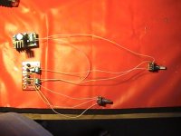
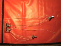
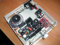
Attached is the LDRs and board from Uriahs kit.
Mine ended paired with a DCB1 buffer with the bypass capacitor mod, the CCS current crancked up and Takman resistors. It sounds and measures extremelly well.
In my volume control I havent used the 5k pot, because I don't want a balance control. So i placed another 200ohm trimmer and a pair of 100ohm resistors with them.
Attached is the LDRs and board from Uriahs kit.
Attachments
When I first built the MyRefC, I tested it using a 8ohm resistor, the heatsinks were much hotter than when I tested it using a real 8 ohm speaker. On the speaker, the heatsinks were barely warm and way way cooler than using a 8 ohm resistor. My speaker is as single driver, so no crossover. Can anyone explain to me this?
When I first built the MyRefC, I tested it using a 8ohm resistor, the heatsinks were much hotter than when I tested it using a real 8 ohm speaker. On the speaker, the heatsinks were barely warm and way way cooler than using a 8 ohm resistor. My speaker is as single driver, so no crossover. Can anyone explain to me this?
Were you using the same test signal in both situations?
- Status
- Not open for further replies.
- Home
- Group Buys
- MyRef_C with Ultimate BOM