To my real friends, the majority of this thread readers
I want to inform you all that i am not reading Pavel Macura and Eva posts anymore..for repeated times i felt not educated, not nice and not friendly, reason why i give up to read their posts....more often they come to bother, not to really help..when they explain something you see they try to humiliate, to say they know more and that you know less.
Several friends readed them criticising me in other threads....forum management already knows that.... and there are others forum users, alike me, that use to complain about their behavior/arrogance.
If they are beeing kind , for a while, do not trust...it is just a strategy.
I will be feeding the thread, not reading and ignoring them..... no more chance to them.
Mr. Andrew T is readed when i found he is in a stable phase of his life..when his mood is reasonable...when he start to be agressive then i use to give a break to read this posts.. the man is competent, a living electronic encyclopedia, helpfull and usefull in most of the times..... from time to time he is lovely, dancing to help to collect money to help people having serious diseases....very nice thing he did.
You know, we are lucky..forum has thousands of guys, and only three or four are not entirelly fine.... a bunch of them already abandoned the forum or were kicked out...this continues to be a lovely place to be.
The amplifier works fine....the Dx Blame ST, this thread subject, also the supply was tested and the crowbar is there, more for psychological support reasons, than for a real need... it is very possible the crowbar will never have a chance to work..... usually these supplies does not present defects, i have assembled hundreds those last 35 years.... when the suggested voltages are applied, and suggested loads (3 amperes maximum each rail and 48V in/35 Volts out) are applied, the supply goes working without any stress.
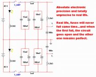
I cannot guarantee electronics against bad use, also if the guy decide to use it underwater, and without a waterproof case.... the fuses are there to avoid fire, if an accident happens.
Funny the difference of theory and reality..ahahahaha..fuses, in the simulator, opens same time...open both of them....ahahahahah!... real life this never happens.
regards,
Carlos
I want to inform you all that i am not reading Pavel Macura and Eva posts anymore..for repeated times i felt not educated, not nice and not friendly, reason why i give up to read their posts....more often they come to bother, not to really help..when they explain something you see they try to humiliate, to say they know more and that you know less.
Several friends readed them criticising me in other threads....forum management already knows that.... and there are others forum users, alike me, that use to complain about their behavior/arrogance.
If they are beeing kind , for a while, do not trust...it is just a strategy.
I will be feeding the thread, not reading and ignoring them..... no more chance to them.
Mr. Andrew T is readed when i found he is in a stable phase of his life..when his mood is reasonable...when he start to be agressive then i use to give a break to read this posts.. the man is competent, a living electronic encyclopedia, helpfull and usefull in most of the times..... from time to time he is lovely, dancing to help to collect money to help people having serious diseases....very nice thing he did.
You know, we are lucky..forum has thousands of guys, and only three or four are not entirelly fine.... a bunch of them already abandoned the forum or were kicked out...this continues to be a lovely place to be.
The amplifier works fine....the Dx Blame ST, this thread subject, also the supply was tested and the crowbar is there, more for psychological support reasons, than for a real need... it is very possible the crowbar will never have a chance to work..... usually these supplies does not present defects, i have assembled hundreds those last 35 years.... when the suggested voltages are applied, and suggested loads (3 amperes maximum each rail and 48V in/35 Volts out) are applied, the supply goes working without any stress.
I cannot guarantee electronics against bad use, also if the guy decide to use it underwater, and without a waterproof case.... the fuses are there to avoid fire, if an accident happens.
Funny the difference of theory and reality..ahahahaha..fuses, in the simulator, opens same time...open both of them....ahahahahah!... real life this never happens.
regards,
Carlos
Attachments
Last edited:
I want to inform you all that i am not reading Pavel Macura and Eva posts anymore..for repeated times i felt not educated, not nice and not friendly, reason why i give up to read their posts....more often they come to bother, not to really help..when they explain something you see they try to humiliate, to say they know more and that you know less.
Carlos
When someone is wrong, i don t hesitate to tell him about my feelings.
You would be right, but it happens that you also critisized other people
designs , with no technical explanation other than "it doesn t sound
well in my tries"..
At least, Eva and Pavel use worthy technical explanations, while
all the critics that you made in differents threads are baseless
and with no technical value, as it was only a matter of
denigrating other people designs.
Just stop feeding your ego, and you ll progress a lot..
If what i say doesn t suit you, just put me on your ignore list
as well......
Dear Carlos,
You remind me of a little child, closing its eyes, thinking nobody sees him.
Do you really think your designs will make more sense, be more reliable and stable, if you keep ignoring people who are proven in electronics, trying to warn you about obvious mistakes and erroneous solutions in your schematics?
And who made you a doctor in charge, deciding who is in its stable phase in life? What phase of life are you in, Carlos?
Also remove watter from the house..as the guy may go to have a shower, will stop breath during the bath and will suicide himself thinking should not breath air when having a shower.
Maybe will have to remove gaz from the house too, as to prepare a coffee, the guy may put fire in the entire home to produce heat to boil watter.
Also, that idiot builder will never listen to the amplifier he built...the unit is grounded!.... so...cannot be free to play music.
Also, Pliedtka, do not spend your time explaining things to idiots..they cannot understand and because of that will think the idiot is you...better to ignore them.
Inside Psychiatric hospitals, mad houses, the crazy ones use to say the doctors are the ones are really sick.... also because they do not know when are talking with Napoleón Bonaparte!
ahahahahahah!
regards,
Carlos
Ground fault interrupters are mandatory in many countries (at least in developed ones), to detect electricity leakage and remove mains supply form the house.
Gas leakage and fire detectors are also mandatory in many cases.
I don't think water leakage detectors are an usual thing, but cutting water supply could also avoid many difficult situations. If I remember properly, Carlos told that he suffered that at home recently.
I think the quick blow fuse datasheet posted by PMA tells it all. I wonder if Carlos has ever taken a look at such a datasheet before specifying a fuse size. Ideal fuses in circuit simulators always blow exactly at rated current, but real fuses are a bit different 😀
Even a quick 3.15A speaker fuse will take 4.65A for 1 hour minimum (and 6.3A for 30 min maximum) before blowing.
What worries me about these threads is the difussion of false electronics knowledge, bad design practices and non-scientific methods, reducing the overall reliability of the information posted in the forum. That's why I feel the need to show the opposite point of view at times.
Last edited:
Thank you Wahab and Quator.... well boys... i continue working
rigth now i am uploading a video to youtube showing you the supply performance.
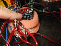
I am using a simple bridge rectifier, 10 thousand plus 10 thousand microfarads filter (only) and a 48 plus 48 volts DC from the toroidal transformer.
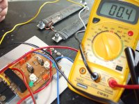
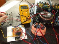
This 48 plus 48 volts are entering the symetrical Dx Voltage Regulator (really it is Ampex voltage regulator, made for Professional Video Tape machines, open reel ones).... the voltage regulator had the output adjusted to 36.2 volts (more or less this)... two 7 ohms / 70 watts resistances were place to load both rails same time...and this was 5 amperes each rail, because voltage dropped down to 35 plus 35 volts.
The power drained was 175 watts each rail...total of 350 watts, the voltage drop was around 1.2 volts, and this is less than 5 percent...and observe the input voltage, how much dropped.... good transformer this one.
Regulator heatsink got hot (around 50 degrees celsius), but this is continuous drain..audio use to be average..so, this will work fine.
Output resistances, of course, started to overheat,as they are undersized to this work.
This current, corresponds to two Dx Blame ST amplifiers, working full power, over 4 ohms loads, continuous sinusoidal signal, undistorted and unclipped....producing 100 watts rms each channel.
I am suggesting this supply, IF you have a bad transformer, and IF you need to reduce voltage in order to match your power amplifeir needs..the supply output is adjustable and stabilized in 5 percent...also you can use capacitance multiplier adding an electrolitic condenser in the position suggested some posts before this one....i have suggested to use 25000uf each rail as filters in the rectifier side...and more 10 to 15000 thousand each rail at the regulator output, to provide electrons reserve to be send to the amplifier when needed...if the regulator is not so fast..electrons going out from the electrolitic are fast.
images attached, and soon i will post the youtube video link.
Build things folks..this forum is Do it Yourself..it is to produce something, not only ideas and discussions.
regards,
Carlos
rigth now i am uploading a video to youtube showing you the supply performance.
I am using a simple bridge rectifier, 10 thousand plus 10 thousand microfarads filter (only) and a 48 plus 48 volts DC from the toroidal transformer.
This 48 plus 48 volts are entering the symetrical Dx Voltage Regulator (really it is Ampex voltage regulator, made for Professional Video Tape machines, open reel ones).... the voltage regulator had the output adjusted to 36.2 volts (more or less this)... two 7 ohms / 70 watts resistances were place to load both rails same time...and this was 5 amperes each rail, because voltage dropped down to 35 plus 35 volts.
The power drained was 175 watts each rail...total of 350 watts, the voltage drop was around 1.2 volts, and this is less than 5 percent...and observe the input voltage, how much dropped.... good transformer this one.
Regulator heatsink got hot (around 50 degrees celsius), but this is continuous drain..audio use to be average..so, this will work fine.
Output resistances, of course, started to overheat,as they are undersized to this work.
This current, corresponds to two Dx Blame ST amplifiers, working full power, over 4 ohms loads, continuous sinusoidal signal, undistorted and unclipped....producing 100 watts rms each channel.
I am suggesting this supply, IF you have a bad transformer, and IF you need to reduce voltage in order to match your power amplifeir needs..the supply output is adjustable and stabilized in 5 percent...also you can use capacitance multiplier adding an electrolitic condenser in the position suggested some posts before this one....i have suggested to use 25000uf each rail as filters in the rectifier side...and more 10 to 15000 thousand each rail at the regulator output, to provide electrons reserve to be send to the amplifier when needed...if the regulator is not so fast..electrons going out from the electrolitic are fast.
images attached, and soon i will post the youtube video link.
Build things folks..this forum is Do it Yourself..it is to produce something, not only ideas and discussions.
regards,
Carlos
Attachments
Last edited:
I will take a look on that when building the "crowbar" circuit.
It is working in the simulator.
I misunderstood the purpose of the circuit, sorry. However it's not good crowbar as the transistors will fail before the fuses do, due to SOA limitation - the circuit shown (in your latest schematic) like a shunt regulator limiting voltage, so a lot of current will flow while there is a high voltage over the transistor. Based on the datasheet, it clearly violates the second breakdown of the power transistor, and it will fail short. Why not use SCR's and a zener, the classic crowbar?
Good Ilimzn.... post the crowbar circuit you suggest
Then i will suggest people to use your crowbar....please, post one tested..something guaranteed.
Really, when we produce shorts in the output, the current is enormous and may kill transistors...SCR is a better idea.
In my personal case, i will not even use protections..but i think to forum folks may be a good idea, some of them (majority) is deeply skilled, but we have novices too.
regards,
Carlos
Last edited:
Carlos, I think you should forget about the crowbar/thyristor blowing fuses in the supply line which in turn blows the speaker output fuse. In practice it is guaranteed not to happen 100% of times.
High resistance of a smaller rated fuse in the output line will negatively impact damping factor. Fuses often introduce sonic colouration. Different brands will introduce varying levels of distortion. They are not always reliable, ie., the semiconductor will blow and take the fuse with it. High resistance may help with increasing Qts of a full range driver but will be bad for multi-way speakers with passive crossover components.
Just go in for a simple DC detector and a speaker relay solution. My two cents.
Good Samuel...i am already producing the protector circuit
Soon the board will arrive from a friend.
And them i will use it.
thank you,
regards,
Carlos
Soon the board will arrive from a friend.
And them i will use it.
thank you,
regards,
Carlos
it will never blow under ideal conditions. Fuses are usually rated with their nominal current, i.e. the max. current they will be able to deliver indefinitely without melting. 😉Take a look at fuse melting time charts from their manufacturers. A typical slow 3A fuse will take many hours to blow at 3A
regards
Last edited:
High resistance of a smaller rated fuse in the output line will negatively impact damping factor. Fuses often introduce sonic colouration. Different brands will introduce varying levels of distortion. They are not always reliable, ie., the semiconductor will blow and take the fuse with it. High resistance may help with increasing Qts of a full range driver but will be bad for multi-way speakers with passive crossover components.
Hmmm... is there any similar influence from the fuses used in the supply rails?
The supply rail fuses are before the amplifier and it's NFB. They have virtually no effect on the sound quality delivered to the speaker.
If the supply rail fuses are selected to just pass valid audio to valid loads then they should not suffer nuisance blowing. They will probably not survive full power testing with medium term sinewave signals.
Selecting fuse rating like this should then ensure that the fuse/s will rupture if a longterm current overload exists.
This is hopefully sufficient to protect robust speakers. It will not save the semiconductors.
That's where short term and medium term protection systems become more useful.
If supply rail fuses are fitted there must be a back up system to detect and isolate DC from the output. This could be designed into the amplifier or can be added on to the amplifier.
Then i will suggest people to use your crowbar....please, post one tested..something guaranteed.
Really, when we produce shorts in the output, the current is enormous and may kill transistors...SCR is a better idea.
In my personal case, i will not even use protections..but i think to forum folks may be a good idea, some of them (majority) is deeply skilled, but we have novices too.
regards,
Carlos
Very simple, a zener for maximum voltage in series with a small resistor (100 ohms or so) from SCR anode to gate, and a resistor on the order of k ohms from gate to cathode. Then connect the whole thing anode to positive, cathode to negative point of required power supply.
A large zener is not needed as when the SCR is triggered, it automatically reduces it's voltage to some 1-2V, so the full voltage of the zener is only present for a very short time over it. Of course, the circuit can be somewhat refined but even this very simple one will do.
Thank you Ilimzn...... well my dear Soundbuster, do not send shame on me man!
Sound, my dear, do not worry, or solder a small piece of wire bellow the board, a very thin wire, to guarantee low resistance..these wires used in micro shielded cables..they melt with 100 mA or less...then this effect people said can be minimized or removed.... when people comes with these stories i use to say will solder a wire and them they feel happy.
I feel sad you believe in such things Sound...you were my student for a couple of years and i felt you with immunity related such kind of things...i see i failed to instruct you...or you may be kidding answering this.
"Procurar piôlho na cabeça de careca"...."search of lices in a bald man's head"...no hairs means no lices..so..means, searching for inexistium, myth, stories.
These things, we just read and them we go on with our target, without discuss...i just cannot be silent watching you buying such kind of things.
Let me know if you really believe that, ... you should be kidding Doctor Sound, you are an engineer!...if you're not kidding, talking serious, then i will offer you, as a prize, a big chance...today is your day!......... i have a capacitor here, golden colour...made of pure gold gazes dampened with spiritual fluids that makes sound filtered....and i can sell you by a very special super low price.... 10 thousand dollars.... the capacitor only high inteligent quocient guys can see...you for sure will see it.... also you can connect to the circuit because it has some spiritual entities that fix the leads using magic ropes that will keep them in place in our board without the use of solder.
Do not tell folks...only me and you will know that...only fat and strong electrons, the ones turns clockwise will cross this capacitor.
This capacitor works for medium frequencies early morning..... will be good for basses during the nigth..and depending the weather it can spell a product that kill mosquitoes and also send your wife mother to hell with one way ticket!
ahahahahahah!
regards,
Carlos
Last edited:
Just asking, Carlos... rail fuses are used everywhere so, statistically, are not harmfull. Hadn´t realized yet the possible reason. About capacitors, I will try another flavours, opportunely.
Ahahahahah!....fine dear Sound...good.
Fuses have more than hundred years old..they are good..avoid fire!
regards,
Carlos
Fuses have more than hundred years old..they are good..avoid fire!
regards,
Carlos
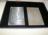
Some news from Germany...
Rudi´s PCB-layout now is playing stable like the Rocky Mountains, the rollercoster is gone away 🙂
I dónt know why, nothing was changed, this amp is playing daily, and become better and better ???!
Rudi´s PCB-layout now is playing stable like the Rocky Mountains, the rollercoster is gone away 🙂
I dónt know why, nothing was changed, this amp is playing daily, and become better and better ???!
Must be something about the condensors or soldering....i have tested 9,6V bias...you will not hear this, not good, but stable 🙂) Now i have 7,6V and want to go to 6,9, this may be good for sanken 2SA1216/2SC2922, or something between this...
and what is about shy bass?? sorry, this amp is playing this at the point, without any problems ;-)
I have new PCBs, i will build them as blame st, but this may take some time.
and what is about shy bass?? sorry, this amp is playing this at the point, without any problems ;-)
I have new PCBs, i will build them as blame st, but this may take some time.
Attachments
Last edited:
Why are the areas with name and amp type connected to live paths, when no components are mounted to them ?
- Status
- Not open for further replies.
- Home
- Amplifiers
- Solid State
- Dx Blame ES .... based into the Blameless, i am trying a new amplifier