Here a simulator one..... but i will build to be sure this works fine.
regards,
Carlos
You are missing a resistor in the emitter line of the darlington (current sink)
2N5401 and 2N5551 are not recomended..... now a days i am scared about these transistors...i had too much troubles with them.
2SC4793 and 2SA1837 can be used as drivers.
But i have not tested.... so i cannot ensure they will be fine.
Avoid MJE350/340.... also i have tried MJ15032 and complementary and found not good too.
regards,
Carlos
Sorry for the noob question, but is the 2SC4793/2SA1837 supposed to replace the BC546/BC556, BD13/BD140 or both?
the 1837/4793 are medium power transistors that suit driver duty in an audio power amp. They would drive the final output pair.is the 2SC4793/2SA1837 supposed to replace the BC546/BC556, BD13/BD140 or both?
the 1837/4793 are medium power transistors that suit driver duty in an audio power amp. They would drive the final output pair.
How about the BC546/556? Any viable replacements for those?
bc546/556 are the higher voltage versions of bc 549/550/559/560.
If the extra voltage ability is not required then any of the other bc listed would substitute.
The bc come ungraded, or a, b, or c.
C is generally available in 550/560 and usually adopted for LTP duty and other general purpose low power, high gain, medium frequency uses.
Do you have the datasheets for all the transistors that are needed? All the data is in there to allow you to compare with alternatives.
bc546/556 are the higher voltage versions of bc 549/550/559/560.
If the extra voltage ability is not required then any of the other bc listed would substitute.
The bc come ungraded, or a, b, or c.
C is generally available in 550/560 and usually adopted for LTP duty and other general purpose low power, high gain, medium frequency uses.
Andrew, beg to agree and desagree at same time...
550/560 are 45V VCE, so they suit the best on the
alternative list, providing the rail are limited to about
+-40V, to keep a (little) margin.
549/559 are 30V VCE and should be used accordingly,
i.e, no more than +-25V rails.
2SC4793 and complementary substitutes BD139/140
These ones are not perfect substitutes because they are to be used under higher voltage..but works fine.
BC550/560 can be used too to substitute BC5456/556
regards,
Carlos
These ones are not perfect substitutes because they are to be used under higher voltage..but works fine.
BC550/560 can be used too to substitute BC5456/556
regards,
Carlos
Thank you Ilimzn
I will take a look on that when building the "crowbar" circuit.
It is working in the simulator.
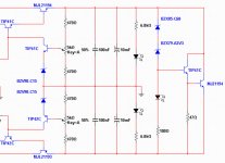
The way it is all current crosses the first darlington base to emitter, goes directly, without losses, without share current, into the MJL21194 power transistor base to emitter junction... the absent resistance would steal some precious current...i am reducing the maximum i can to reduce zener current.
I want to reduce the zener current to avoid to use a big 5 watt zener..so...all current i can save will be good.... you know, not wasting some current to cross this first transistor emitter resistance.
The two diodes, the two transistors base to emitter junctions, will develop the needed potential i need to drive them on.... and i need to saturate them, at same time trying not to provide too much current to the first darlington base.
I hope you understood what i mean.
regards,
Carlos
I will take a look on that when building the "crowbar" circuit.
It is working in the simulator.
The way it is all current crosses the first darlington base to emitter, goes directly, without losses, without share current, into the MJL21194 power transistor base to emitter junction... the absent resistance would steal some precious current...i am reducing the maximum i can to reduce zener current.
I want to reduce the zener current to avoid to use a big 5 watt zener..so...all current i can save will be good.... you know, not wasting some current to cross this first transistor emitter resistance.
The two diodes, the two transistors base to emitter junctions, will develop the needed potential i need to drive them on.... and i need to saturate them, at same time trying not to provide too much current to the first darlington base.
I hope you understood what i mean.
regards,
Carlos
Last edited:
This gonna be adjusted while building and testing
Zener is 200mW unit..this is reasonable....i have installed the emitter resistance and a red Led that will show when crowbar will be on, means fuses are already opened...maybe i will install resistances in parallel with the fuses...and leds...so..when fuses are burned, opened circuit, then leds will ligth "on".
regards,
Carlos
Attachments
Hi,
a single crowbar across both supply rails may, if triggered, leave one rail fuse intact.
Will DX ST output near zero offset if one or other supply rail is down?
a single crowbar across both supply rails may, if triggered, leave one rail fuse intact.
Will DX ST output near zero offset if one or other supply rail is down?
Power amplifier output is fused.
If one supply fuse remains, then that rail voltage will appear in the power amplifier output line...there. in series with the output line to the speaker we should have a 2.5 to 3.0 fuse in series with the speaker.... 35 volts will cross fuse and then will enter speaker coil.... 6 ohms speaker coil (resistance) will drain 5 amperes..this will melt power amplifier output fuse in some miliseconds....but faster than the coil will melt...say..fuse will melt, coil will survive.
If this output line fuse did not melt, the weaker ones, at the power amplifier rails will melt... circuit will be opened..no more current.
regards,
Carlos
Last edited:
In the reality, this crowbar will not be used..it is there
"just in case".....i have made several supplies and they do not present any kind of defect...fuses, in the voltage regulator protects the transistor junctions against accidental shorts or power amplifier failures....so...crowbar is there for bad lucky guys...really, just in case.
Also, my suggestion is to use the voltage regulator with supplies that have 10 or 15 volts than the needed voltage...and this will not kill an amplifier..maybe one rail electrolitic condenser can be damaged and will drain current enougth to open the amplifier rail fuse.... the output fuse is another "just in case"...as rail fuses may burn in advance.
And we cannot forget the transformer primary...the one is also fused.
These Dx amplifiers, usually does not burn fuses, they work fine for decades long without any trouble...fuses are there to protect against bad use, too low impedance loads, shorts in the output and these things...they are alike my home fuses...i had never one damaged, they are automatic and if i can remember i had one burned down the seventies because a big air conditioned damaged.
They avoid fire.... as when we have wrong designs in amplifiers, transistors burns in advance the fuse can melt..they just stop fire..they use to burn when something had already burned in advance, and created the over current to melt the fuse wire some miliseconds latter.
regards,
Carlos
Last edited:
If one supply fuse remains, then that rail voltage will appear in the power amplifier output line...there. in series with the output line to the speaker we should have a 2.5 to 3.0 fuse in series with the speaker.... 35 volts will cross fuse and then will enter speaker coil.... 6 ohms speaker coil (resistance) will drain 5 amperes..this will melt power amplifier output fuse in some miliseconds...
In milliseconds? You must be joking, or using very low current high resistance fuse.
I am not reading Pavel texts anymore....looks not friendly
And i love to keep my good mood untouched.
Not reading, will not bother me...i am not curious anymore... usually is not nice...this way i wil continue laughing all day long... in special because several folks have built my amplifier..and many others will build..thousands are visiting the thread... happy guys use to come here.... thank's God, mumified and bad mood ones use to keep some distance.
Carlos
Attachments


Last edited:
PMA is right.
Fuses are not reliable for semiconductor protection, unless the current rating of the fuse is much lower than the current the semiconductors can reliably source or sink.
Fuses are not reliable for speaker protection either, particularly for DC protection. Many faults resulting in DC at the speaker will not put the full rail voltage into the voice coil, particularly due to power supply sag. In the past I have repaired many amplifiers with DC faults whose fuses didn't blow (resulting in cooked voice coils). This imposes the use of a fuse with a low current rating, which will exhibit a highly variable resistance depending on the rms current going through it, in other words, distortion (and the risk to blow it during loud music passages or strong action scenes in movies).
Amplifier designers stopped using fuses for protecting speakers and power semiconductors many years ago. Nowadays, in audio amplifiers, fuses are mostly used to protect power supply transformers and wiring, things that can whitstand overloading for long times.
A regulated power supply without proper V/I current limit is also a crazy thing. In case of overload, the pass transistors will fail shorted from collector to emitter, putting the full input voltage on the output. This may lead to the failure of more transistors.
The result of too high rail voltage on an amplifier with bootstrapped VAS and a 100V VAS transistor is likely to be a short from C to E in VAS transistor. In other words, DC into the speaker.
So a brief short circuit on the speaker output of one channel may result in the destruction of the whole DX amplifier.
Additionally, a missing negative supply rail will make the amplifier dump most of the positive rail directly into the speaker (due to the bootstrapped VAS design, which was used back in 1970s because it costed much less than a two transistor current source).
Amplifiers from 1970s behaved like that because adding protection circuits with dozens of transistors was too expensive back then. But now we are in 2010, standard integrated circuits and transistors cost only a few cents (computer CPU chips have millions of transistors in them). Now the only problem are lazy/stubborn circuit designers (and people that are still living in 1970s).
The first production batches of my latest amplifier design are now being sold. It can do 75 amperes peak output current into any load impedance, including a short. It can work into a short circuit load all day long. It can handle shorts to the rails too. In fact, shorting output terminals is part of the adjustment procedure at the factory. This is more or less what you should expect from something designed in 2009/2010 😀
btw: SMD allows to include the amplifier circuit plus all the protection circuits into the same PCB space that would be required for the amplifier only if thru-hole components were used.
Last edited:
Ol'good '88 Sima 3050
only 50W/8 ohm, not fuses on rails, no current limiting, only a fuse at spkr. out. Transparent, bright, OK amp. Big caps, big transformes. But after I cameback from visiting my sis, which is 1hr drive to Nelson Pass (Papa Smerf, I call him) place, I found the R-ch is caput. Some morron figure it out that it doesn't have DC Protection, no clipping indicator and no input Cap. I don't like current limiters 'cause in case of small amps they sound like crap at levels close to clipping and it complicates things, I turn the volume down if it clips. But they blow it anyway , maybe the fuse was a bit too slow, or there was not enough cooling. 😕 So amps sometimes have to be also idiot proof. How about relays at V+, V- so the voltage will be taken of in case something wrong happens. Just a thought 😉
only 50W/8 ohm, not fuses on rails, no current limiting, only a fuse at spkr. out. Transparent, bright, OK amp. Big caps, big transformes. But after I cameback from visiting my sis, which is 1hr drive to Nelson Pass (Papa Smerf, I call him) place, I found the R-ch is caput. Some morron figure it out that it doesn't have DC Protection, no clipping indicator and no input Cap. I don't like current limiters 'cause in case of small amps they sound like crap at levels close to clipping and it complicates things, I turn the volume down if it clips. But they blow it anyway
, maybe the fuse was a bit too slow, or there was not enough cooling. 😕 So amps sometimes have to be also idiot proof. How about relays at V+, V- so the voltage will be taken of in case something wrong happens. Just a thought 😉Attachments
Take a look at fuse melting time charts from their manufacturers. A typical slow 3A fuse will take many hours to blow at 3A, even at 5A it will take 1-3 hours to blow. These fuses are intended to suppress big overloads only. Fast acting fuses are better, but they can blow during normal operation due to signal peaks.
But some people use fuses (and many other parts) without knowing how they really work...
Proper V/I limiters and DC fault detectors will never be activated during normal amplifier use. Adding these circuits without disturbing the amplifier during normal operation is a matter of designer skills. Some can, some can't 😉
Last edited:
To be idiot proof we have to remove AC mains from the house
Also remove watter from the house..as the guy may go to have a shower, will stop breath during the bath and will suicide himself thinking should not breath air when having a shower.
Maybe will have to remove gaz from the house too, as to prepare a coffee, the guy may put fire in the entire home to produce heat to boil watter.
Also, that idiot builder will never listen to the amplifier he built...the unit is grounded!.... so...cannot be free to play music.
Also, Pliedtka, do not spend your time explaining things to idiots..they cannot understand and because of that will think the idiot is you...better to ignore them.
Inside Psychiatric hospitals, mad houses, the crazy ones use to say the doctors are the ones are really sick.... also because they do not know when are talking with Napoleón Bonaparte!
ahahahahahah!
regards,
Carlos
Last edited:
- Status
- Not open for further replies.
- Home
- Amplifiers
- Solid State
- Dx Blame ES .... based into the Blameless, i am trying a new amplifier