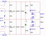
I have changed driver resistances in order to use 200mW zener diodes
These ones are easier to find in Brazilian shops or dismounted sets (supplies from junk).
You can keep the previous schematic if you want, or to use this one..both works fine, voltage drop is 100 milivolts when draining 3A, this means 0.3% voltage drop.
Supplies, without regulators, voltage drop use to be 10 to 20 percent...so, it is an enormous advantage, even considering the worst case.
regards,
Carlos
Attachments
Dx symetrical voltage regulator, stabilizer,step down DC to DC converter
Nice names..it is an electronic control only.
I know transistors there are all NPN..they are there only to adjust lengthes.... the supply is not ready.
I am using Leds too...i will explain latter.
Carlos
Nice names..it is an electronic control only.
I know transistors there are all NPN..they are there only to adjust lengthes.... the supply is not ready.
I am using Leds too...i will explain latter.
Carlos
Attachments
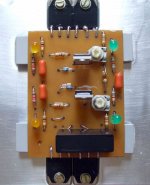
I have included Led in the supply...for monitoring purposes
the green ones, in the output, will not flash...will have constant brigth, as voltage there will be constant.
The Yellow ones are before the electronic stabilizer, so, they will flash, brigth will glow high and low, depending the voltage drop you gonna have there.
regards,
Carlos
the green ones, in the output, will not flash...will have constant brigth, as voltage there will be constant.
The Yellow ones are before the electronic stabilizer, so, they will flash, brigth will glow high and low, depending the voltage drop you gonna have there.
regards,
Carlos
Attachments
No simulator, nor specifications, nor calculations, nor circuit analisis
nothing can give you this.... only a real listening test:
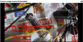
YouTube - Csöves single ended VS Quad405
Any other way to evaluate amplifier is non sense...audio is evaluated listening, and by human ears, nor microphone nor computer......just because audio was made for (should be) for humans...not for instruments.
When designers produce an amplifier, if they are not crazy, they do that for humans, as i could never testimony an spectrum analiser together an osciloscope shopping for audio amplifiers.
You see (listen), the huge difference, and the Quad is famous, has interesting ideas applied, lovely (awfull) operational amplifiers in the input..... a very good circuit, very good specifications, had lovely reviews, was sold around the world as beeing the sonic "Mercedez Benz" or the sonic "Rolls Royce".
You see the lovely Quad when compared to a very simple tube amplifier... sounding dull, without brigth, without presence, almost changing the sound nature..... just awfull....... but you will never realise this just listening to the Quad..will die deeply submerged in the ignorance (not knowing), thinking that have a special piece of sonic jewellery when have a big lemmon!
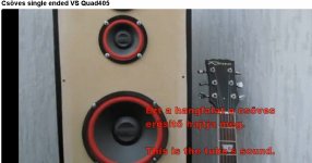
The comparison is not absolutelly fair...not well made... Quad is not so bad that way...the problem is the speaker position, both in corners, this increase the bass response to the tube..that is very weak in bass.... also...increase the bass response to the Quad..and this one is not weak in bass... result!.... Quad was boomy..undefined...just awfull!
Also, the test was not performed with a single speaker.... can you guarantee those two speaker are sounding the same?....it is possible, but not guaranteed..maybe one driver is damaged...and what about the condensers inside the speaker..the passive crossover?....are them having leakage... were replaced by new ones...in both speakers?
Also, and much more important...the tube is receiving audio source directly...the Quad is entering the input plugs..there are switches, pré amplifiers..and all stuff to "kill sonics"....so...the comparison is not decent, not fair, not precise, not honest, not competent.
It is very clear, despite all disadvantages to Quad 405, the sound was too much bad in comparison... even having disadvantages...the tube beated without doubts.
This would never happens with my Blame (Blameless).... for sure it can match the tube amplifier.... would never loose that way....and i would never produce so bad testing..the procedure is absolutelly wrong..unfair.
Even beeing unfair... we can see the huge difference...i do not know exactly, but even fixing these errors..the tube amplifier would best the Quad 405..that's my opinion.
Also..observe the speaker, it is home made...look the screws and you will see this was not made by a factory...this is something DIY..... i cannot guarantee if this speaker is flat or not..maybe, it was "tuned" to be complementary to the tube amplifier...and not good to the Quad 405.... there are folks that use to "twist" the reality to continue deep submerge in their illusions...so..it is possible the speaker is not even flat!..... also.... i could not see the Quad 405...is the amplifier in comparison a real Quad?.... a good Quad?... or something tweaked for sonics by a non skilled guy that killled the Quad performance?
I am sure the Dx Blame ES can match this tube amplifier.... will not be the winner, but may match...tube amplifier are vastly better when compared to transistors...i am not building tubes, because i cannot afford to do that, i have not parts...but i have the know how... i have born in 1951 and i have assembled some tube amplifiers, including Linear Amplifier to Radio Amateurs.
regards,
Carlos
nothing can give you this.... only a real listening test:
YouTube - Csöves single ended VS Quad405
Any other way to evaluate amplifier is non sense...audio is evaluated listening, and by human ears, nor microphone nor computer......just because audio was made for (should be) for humans...not for instruments.
When designers produce an amplifier, if they are not crazy, they do that for humans, as i could never testimony an spectrum analiser together an osciloscope shopping for audio amplifiers.
You see (listen), the huge difference, and the Quad is famous, has interesting ideas applied, lovely (awfull) operational amplifiers in the input..... a very good circuit, very good specifications, had lovely reviews, was sold around the world as beeing the sonic "Mercedez Benz" or the sonic "Rolls Royce".
You see the lovely Quad when compared to a very simple tube amplifier... sounding dull, without brigth, without presence, almost changing the sound nature..... just awfull....... but you will never realise this just listening to the Quad..will die deeply submerged in the ignorance (not knowing), thinking that have a special piece of sonic jewellery when have a big lemmon!
The comparison is not absolutelly fair...not well made... Quad is not so bad that way...the problem is the speaker position, both in corners, this increase the bass response to the tube..that is very weak in bass.... also...increase the bass response to the Quad..and this one is not weak in bass... result!.... Quad was boomy..undefined...just awfull!
Also, the test was not performed with a single speaker.... can you guarantee those two speaker are sounding the same?....it is possible, but not guaranteed..maybe one driver is damaged...and what about the condensers inside the speaker..the passive crossover?....are them having leakage... were replaced by new ones...in both speakers?
Also, and much more important...the tube is receiving audio source directly...the Quad is entering the input plugs..there are switches, pré amplifiers..and all stuff to "kill sonics"....so...the comparison is not decent, not fair, not precise, not honest, not competent.
It is very clear, despite all disadvantages to Quad 405, the sound was too much bad in comparison... even having disadvantages...the tube beated without doubts.
This would never happens with my Blame (Blameless).... for sure it can match the tube amplifier.... would never loose that way....and i would never produce so bad testing..the procedure is absolutelly wrong..unfair.
Even beeing unfair... we can see the huge difference...i do not know exactly, but even fixing these errors..the tube amplifier would best the Quad 405..that's my opinion.
Also..observe the speaker, it is home made...look the screws and you will see this was not made by a factory...this is something DIY..... i cannot guarantee if this speaker is flat or not..maybe, it was "tuned" to be complementary to the tube amplifier...and not good to the Quad 405.... there are folks that use to "twist" the reality to continue deep submerge in their illusions...so..it is possible the speaker is not even flat!..... also.... i could not see the Quad 405...is the amplifier in comparison a real Quad?.... a good Quad?... or something tweaked for sonics by a non skilled guy that killled the Quad performance?
I am sure the Dx Blame ES can match this tube amplifier.... will not be the winner, but may match...tube amplifier are vastly better when compared to transistors...i am not building tubes, because i cannot afford to do that, i have not parts...but i have the know how... i have born in 1951 and i have assembled some tube amplifiers, including Linear Amplifier to Radio Amateurs.
regards,
Carlos
Attachments
Last edited:
125 hours operating, almost continuously...during the night power is reduced to 5W
and connected to a load..... not to generate heat in my sleeping room...my place is hot..weather is hot those last days.
During day it is playing around 5 watts peaks..from time to time i increase till the maximum to listen some thunder basses.
Jet plane sounds injected (youtube videos) and sound generators too...the amplifiers is rock stable.
Triple Dx Guarantee goes to the Dx Blame ST..... the only risk you have is to assemble parts wrong way..... the amplifier will work fine since the first moment you flip the power switch on..... pré adjust bias trimpot to 160 ohms.... you may find 2.2 volts (22mA)..then go increasing till 4.7 volts...or other current you want to adjust.
Check if you have current in the power emitter resistances...there you should read, at least, 1 milivolt.... 3 to 4 milivolts are excelent...more than that will be waste of energy....with unobtanium audio advantages.
regards,
Carlos
Attachments
Last edited:
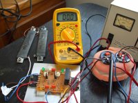
What Dx voltage regulator does.
You will see a small movie.... a 55V bad supply, having enormous voltage drop when loaded, is submited to 2.5 ampere load.
Voltage regulator is adjusted to 35 Volts in the output...and 14 ohms load will be draining current...voltage dropped to 33.6V, so, we had more or less 5 percent loss (1.4V).
Measuring the filters, or the main supply, without regulator, voltage drop was 15 volts.... from 55 to around 40 volts....this means something around 28 percent.
This happened because transformer not good..condensers not enougth, rectifiers very bad (junk from switching power supply, 1N5402).... usually our losses, in the transformer, are around 10 to 15 percent maximum.... regulator made an excelent job this way.. output voltage had to be adjusted to 35 volts because regulator needs, at least 6 volts to work.... difference of voltage from input to ouput... VCE.
5 percent is a big loss....nothing we can compare with 28 percent in the transformer rectifier and filters..but changing the error amplifier transistor by another one with higher gain (this one is 70 of gain) you gonna have much better stabilization..also we need to tune driver current, those 470 ohms original resistances, the ones i am using (last schematic) 1K or 1K2.
In this case...power dissipation in the regulator series pass transistor is the colector voltage minus the emitter voltage...so.... 40 minus 33.6.... 6.4 volts aproximatelly.... current is 2.4 amperes...so... each rail will have 15.4 Watts.... total will be 30.8 watts (aprox.)..... so... a square aluminum blade, 18 centimeters side,will be good.... this aluminium can be bend in the shape you want..also you can use a Industrial heatsink...a 30 watts heatsink for this case.
Each case must be measured to decide the heatsink...also the voltage drop.... Dx amplifiers, the ones operates with 35 volts, drains 2.5 amperes each rail when using 4 ohms loads and 1.25 amperes each rail when using 8 ohms loads... when maximum undistorted power...sinusoidal input signal, unclipped output, 1 Kilohertz input frequency.
Observe this video:
YouTube - Dx voltage regulator working.avi
regards,
Carlos
Attachments
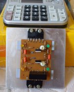
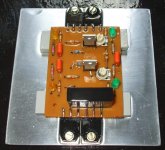
Adjusting the BlameST
After I did the modifications Carlos proposed to make the BlameES "rock-stable", I ajusted my (currently I have only one board) "Lilly-BlameST".
4.70 voltage drop above the 100 Ohm resistance on the negative rail.
4.30 voltage drop above the 100 Ohm resistance on the positive rail.
5mV voltage drop about the emitter resistances.
I will now start and assemble something to get the BlameST connected to my media player.
Best regards - Rudi_Ratlos
After I did the modifications Carlos proposed to make the BlameES "rock-stable", I ajusted my (currently I have only one board) "Lilly-BlameST".
An externally hosted image should be here but it was not working when we last tested it.
4.70 voltage drop above the 100 Ohm resistance on the negative rail.
4.30 voltage drop above the 100 Ohm resistance on the positive rail.
5mV voltage drop about the emitter resistances.
I will now start and assemble something to get the BlameST connected to my media player.
An externally hosted image should be here but it was not working when we last tested it.
Best regards - Rudi_Ratlos
Will play without problems..will sound beautifull.
Congratulations! your board is fine!..so..uncle Charlie was wrong about your boards?....i feel good that i was wrong...wonderfull to be wrong this way.
regards,
Carlos
Congratulations! your board is fine!..so..uncle Charlie was wrong about your boards?....i feel good that i was wrong...wonderfull to be wrong this way.
regards,
Carlos
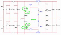
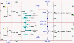
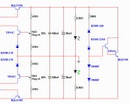
These green condensers uses the capacitance multiplier effect
these two transistors, in the series pass output, are connected darlington mode...gain is high, at least 2500 when current is high.
So..if you insert a 220uf condenser there, the green ones, then you will have this condenser multiplied by the series pass transistor gain, appearing in the output, alike a "virtual" condenser having 550 thousand microfarads.
This keeps voltage steady..but system speed is lowered...say...when you overdrive the system..and when have voltage drops..then to return to the adjusted voltage will delay a lot too....so..will delay to drop..but will delay to return to the previous value of voltage you have adjusted.
It is an option too..... not very good...but can be used too.
regards,
Carlos
Attachments
Regulator Question
Greetings Carlos,
Can you explain why you have different resistances (6k8 and 8k2) connected to the yellow LEDs on your regulator circuit?
Thanks very much.
RKH
Greetings Carlos,
Can you explain why you have different resistances (6k8 and 8k2) connected to the yellow LEDs on your regulator circuit?
Thanks very much.
RKH
Left side is the regulator input..there we will enter with 48 volts
I see..was a mistake..they are 8K2
regards,
Carlos
I see..was a mistake..they are 8K2
regards,
Carlos
Last edited:
In the reality, these resistances are to be adjusted during construction.
to reduce the Led Brigth....so...the left ones, when you experience supply voltage drops, will flick....brigth will change and they will go almost to no brigth...this gonna be your "supply variation ligth monitoring device".
Nice name to a led glow.
regards,
Carlos
to reduce the Led Brigth....so...the left ones, when you experience supply voltage drops, will flick....brigth will change and they will go almost to no brigth...this gonna be your "supply variation ligth monitoring device".
Nice name to a led glow.
regards,
Carlos
Dx regulator...the solution to weak power transformers
Sometimes you have a junk transformer, the output voltage too much high to use together the most used voltages, from 30 to 50 volts... then you can build the Dx regulator.
This will not save your money, as you gonna need one more circuit board, more active devices, voltage adjusting trimpots or potentiometers, and more condensers to connect in the regulator output, to provide a fast to use reserve of electrons.
If regulator is slow..then the condensers charged are not!
It is good as a symetrical adjustable stabilized supply for your laboratory, with this circuit you will be able to feed several projects, replacing the zener for a 8V2 volts you will be able to adjust from 10 volts till your input supply voltage...so, will match a lot of equipments...you can use more output transistors to drain more current with safety, biggers and better heatsinks...a power full transformer in the regulator input.... and depending the voltage adjusted, and your transformer capabilities, you may be able to have 1 to 2 percent maximum error or voltage (drop when loaded)..and this is more than good and more than enougth..when other supplies losses goes from 10 to 15 percent.
Chip amps and operational amplifiers are within this regulator range.... original start in 16 to 17 volts because of zener, but you can reduce this zener to adjust 12 volts too.
Remember that...power dissipated by the series output transistors is the colector voltage minus the emitter voltage (voltage adjusted) multiplied by the current.
The input voltage will drop when the system is loaded....so... doing calculations, take this into your decisions.
If your transformer is powerfull, and voltage drop is not big...then the regulator will work even better, as having less variation of voltage (drop) in the regulator output, the result will be even smaller voltage drop in the output..depending the case you can have 20 milivolts drop...and selecting high gain error correction transistor (the one connected to the adjusting trimpot) then you will have even voltage increase when loaded, in the place to have voltage drop.
You can have a very low noise supply, using capacitance multiplier effect, the green condenser shown in one of my last sketches published a couple of posts back.
Better is to use the correct transformer, a powerfull one that will not have voltage drop when you will be draining 3 amperes each rail (each power amplifier during clipping can suck this ammount of current)...using strong rectifiers and a nice bank of electrolitic condensers...but ..this can be helpfull to use that "junk transformer" you have around, without know what to do with the little monster.
But observe..if your regulator output voltage will be 70 volts..and you decide to adjust the output to 20 volts each rail...then 50 volts will be in the series power transistor colector to emitter...if 10 amperes were drained..then 500 watts of power will be heating the regulator..then you gonna need several output pairs, enormous heatsink...so..this can be used, when you need small voltage drops of 10 or 15 volts maximum, and with small currents..around 2 or 3 amperes.
Regulator transistors must be matched in gain, or you gonna have different voltages in the regulator output while draining same current both rails...more output pairs will need emitter resistances to equalize power to all series pass power transistors.... zener must be 500mW or 1W... resistances 500mW or 1 Watt, and condensers insulating voltage bigger than the input voltage.
Leds are there for monitoring purposes..adjusted to small brigth, small glow..then you will see them almost off when voltage drop in the input (yellow ones) is high..the output leds, the green ones, will not have variations in brigth, as voltage drop in the output is not too much big.
Other transistors can be used..respect maximum voltage, maximum current, and power dissipation only..higher gain units will give you even better regulation.
regards,
Carlos
Attachments
Last edited:
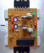
These condenser will give you slow voltage decay.... DC voltage drop
will take some time, while dropping voltage, to reach the real one as consequence of current drain...this may be good..but to increase voltage back again, when load reduce the consumption, will take some time...will be slow again..and this we do not want... we want the supply to decay slowly, but we will dislike the voltage recovery time.
So, it is an advantage and a disadvantage.... depending the case... to AM RF transmitter is fine..but for SSB transmission it is not... i think it is not so bad for audio.
It is optional, try it and tell me what you think.... these condensers, included using paint program, were shown in the schematic that has green 220uF condensers posted several posts back....works as capacitance multiplier, but slows down the whole system.
regards,
Carlos
Attachments
Last edited:
We can have surprises... regulator parts failure, open zener and other failures
may increase your regulator output voltage..and this can be dangerous, depending you input voltage selected.
Dx crowbar is so added. it will senses the ouput voltage, and will produce a 8 ampere short in the regulator output, this will open the fuse..... if this happens with a single rail, then the power amplifier output fuse, the 3A fast blow (to 8 ohms) and the 6A fast blow (to 4 ohms) will interrupt current to speaker.
How this works?
100 ohms will only limit current to the zener and diodes.... when voltage is higher than zener voltage plus 1.2 volts, then the transistor will conduct from colector to emitter..this will produce the output short that will burn the regulator fuse....interrupting the energy supply.
This way, series pass transistor shorted, or other regulator possible failures, will not create you problems.
This Dx crowbar was not tested.... but will be very soon...for sure will work fine, maybe will need some adjustment....the crowbar transistor emitter has a resistance to limit the current, not to kill the transistor.... 10 ampere transistors, more than 64 volts, power units, can be used for this function...leds are there not to allow VBE to increase above 1.2 volts, then protecting the transistor input against over voltage.
Do not forget to set your voltage adjustments mid way prior to first supply power on...or you may be setting too high voltage that will burn your fuses.... another transistor, another crowbar, from positive to negative (more than 70 volts and fuses opened as consequence) can be installed if you want even more protection..... current limiters are not a very good idea.
regards,
Carlos
Attachments
Last edited:
And here, a rail to rail crowbar
Rail voltages are 35 volts...so, adding you have 70 volts.... if one of these rails have increased voltage, as a result of regulator circuit failure or misadjustment, then the total added voltages will exceed the crowbar zener voltage..the power transistor will produce a short from positive to negative, and this will burn supply fuses....both rails will be off...no voltage going to the power amplifier.
regards,
Carlos
Attachments

I'm having difficulties in acquiring the BC546/BC556 and BD13/BD140. Could you recommend good substitutes?
I cannot guarantee, but maybe BC640/639 will work in the differential
2N5401 and 2N5551 are not recomended..... now a days i am scared about these transistors...i had too much troubles with them.
2SC4793 and 2SA1837 can be used as drivers.
But i have not tested.... so i cannot ensure they will be fine.
Avoid MJE350/340.... also i have tried MJ15032 and complementary and found not good too.
regards,
Carlos
Dx voltage regulator, 5% losses instead of 28% voltage drop
The regulation may reach 1 percent, depending the transformer power:
YouTube - Dx voltage regulator, 5% instead of 28% losses.
regards,
Carlos
The regulation may reach 1 percent, depending the transformer power:
YouTube - Dx voltage regulator, 5% instead of 28% losses.
regards,
Carlos
- Status
- Not open for further replies.
- Home
- Amplifiers
- Solid State
- Dx Blame ES .... based into the Blameless, i am trying a new amplifier