Thanks, do I just hook up the feedback to both the 4 and 8 ohm posts both? Sorry for the stupid questions.
Al
If you are inverting the winding the way I described above, then you would use the 4 ohm tap for feedback (because it's really now the 8 ohm tap). I have attached a Hammond diagram modified to illustrate what I mean.
I would assume that you want to use the same tap that Pete used for feedback regardless of which tap you use for your speakers.
Someone correct me if I am wrong here.
Attachments
I must have been smoking something pretty good when I wrote all that. I am completely wrong on several levels...ignore what I said about swapping the secondary. Hook it up as it should be (common on ground, 4 ohm on 4ohm, etc) and use the 8-ohm tap for feedback. The way to invert the phase on a PP OPT is to swap the PRIMARY wires. I suspect Pete has it all figured out for the Edcors. I don't know why he hooked it up that way.
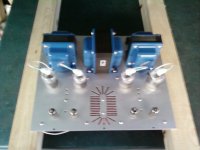
Well ok. I hooked it up as you said earlier and it seemed to work ok on some minimus 7s. I will hook it up the other way before I fire it up again on good speakers. Here here is a crappy cell phone pic. Now I need to give this lady a skirt.
Thanks again for the help,
Al
Thanks again for the help,
Al
Attachments
Thanks I bought it off a guy on ebay. He added a couple of extra things such as holes for plate caps and the extra hole for a binding post. I think he is selling them for 45 bucks. The sink seems to work, after being on for 45 min the plate was barely warm.
Al
Al
Here's my baby:

Not sure if I'm going to stain the wood or not - it's Baltic Birch plywood I picked up for $5 and ripped to size. I'm using brass inserts in the plywood to allow me to screw the top plate down with standard machine screws. Still on the 'to-do' list is a bottom plate with a couple of machined vent holes.
Oh, and FWIW, after the first week, the bias had drifted considerably, so you might want to check your amps. 😕
-D
Link?
Chassis Top Plate Millett DCPP Tube Amplifier - eBay (item 270544142699 end time Mar-16-10 13:38:05 PDT)
You can also search for seller "twingreenmonsters"
-D
Russ have you made any changes to the power supply to accomodate the 6HJ5 tubes or are you using the components that were spec'd. I know that higher voltage rated capacitors are in order and a different transformer.
I used 500V caps for the 47uF ones, but no one makes a 10uF 500V cap that will drop in. The closest you can come would be to stand a Sprague 10uF 500V axial cap on its end and wrap the other lead over (insulated of course), but they are expensive and the board uses a lot of them. So I'll have to stick with 400-450V B+ range for the various tubes I have to try. That will involve a bench supply to figure out the plate and screen voltages. George probably already knows what the 6HJ5s like.
Note that once the operating conditions are understood, R21 may need to be increased to prevent Q1 from frying, depending on the screen voltage that will be needed for the tubes in question relative to the B+. D5,7,8 control that regulator.
Note that once the operating conditions are understood, R21 may need to be increased to prevent Q1 from frying, depending on the screen voltage that will be needed for the tubes in question relative to the B+. D5,7,8 control that regulator.
Looks lovely in black.😀 nice job.Here's my baby:
Not sure if I'm going to stain the wood or not - it's Baltic Birch plywood I picked up for $5 and ripped to size. I'm using brass inserts in the plywood to allow me to screw the top plate down with standard machine screws. Still on the 'to-do' list is a bottom plate with a couple of machined vent holes.
Oh, and FWIW, after the first week, the bias had drifted considerably, so you might want to check your amps. 😕
-D
I just re biased for the first time on your advise, and yes there is some drift, although the balance seems to steady. I might break out the nail polish and lacquer the balance pots.
Simulations in PSUD indicate that the AN-4T360 should yield 450V B+. Screen regulator will be modified for 200V or 250V, depending on what the 6HJ5/6HF5 can take. I'll be adding a winding for the 100VCT bias supply.
Screen regulator will be modified for 200V or 250V, depending on what the 6HJ5/6HF5 can take.
I have stuffed about a dozen different tubes in my board. They all seem to work best at or very near 150 volts. Pete is right on here, more voltage doesn't make any more power, even at the 200 WPC level (6LF6).
George probably already knows what the 6HJ5s like.
The 6HJ5 will work fine with 150 volts on the screen. Plate voltages have been tested up to 525 volts. I found out once already that the 450 volt caps that are in my board get rather angry if I go much higher than this. The tubes can probably handle a little more voltage, but the OPT's that I am using (the ugly ones) are really not rated for this. They are the same transformers I use on the Simple P-P. I haven't blown one yet!
I have stuffed about a dozen different tubes in my board. They all seem to work best at or very near 150 volts. Pete is right on here, more voltage doesn't make any more power, even at the 200 WPC level (6LF6).
Good to know! What are you using for a heatsink on the regulator?
Anteks are on the way...but the bench is occupied right now. 😉
Good to know! What are you using for a heatsink on the regulator?
No regulator, or even power supply yet. I got my red board as a science project. I never planned to make a complete amplifier out of it, hence the decision to put the parts on the same side of the boards as the tubes. As for now I use 3 bench power supplies to run it so everything is completely tweakable.
I got this board because it was a shortcut to explore the "Schaded pentode" circuitry that I first saw in Gary Pimms "Tabor". I have seen that same concept somewhere else, but I can't find it. The Tabor uses a direct coupled design that eliminates the coupling caps at the expense of a complicated power supply. I made a super simple version a while back using 6AQ5's for output tubes because I have a bunch, and some are so ugly that they are only suitable for experiments. Sort of a push pull "free lunch" or "monkey" circuit. It worked, sort of, and I always wanted to get back to it, but I have a whole shelf full of those kinds of circuits.
Now that I have spent some time with this board I have a whole list of experiments to try, some of which require severe circuit modification (mosfets, an additional gain stage), and there are still a few things about this design that I don't understand yet (the tube matching criteria for ultra low distortion, and why it doesn't correlate with sound). Given ample time (fat chance) I would like to do a couple of test boards to explore some of those ideas.
Either way I don't think my red board will see a real power supply soon, if ever.
"to explore the "Schaded pentode" circuitry that I first saw in Gary Pimms "Tabor". I have seen that same concept somewhere else, but I can't find it."
The 50 watt amplifier in the back of the RCA tube manuals uses Schaded pentodes. Some well known manufacturer copied one or more of the RCA designs, maybe that one too.
The 50 watt amplifier in the back of the RCA tube manuals uses Schaded pentodes. Some well known manufacturer copied one or more of the RCA designs, maybe that one too.
As for now I use 3 bench power supplies to run it so everything is completely tweakable.
Duh...yeah sorry I knew that from looking at your pics. I mention it because to keep 150V on the screens, R21 is going to need to be increased to keep Q1's dissipation under control. You are the only person so far that has actually tried higher voltages. Sadly, I do not own a power supply that is rated over 100mA, though I routinely "peg" my Heathkit IP-32 and it seems to survive. One of the Anteks that is on the way will be used to construct a better bench supply (someday). 🙂
Could not resist....
....getting one of Pete's DCPP boards. It arrived yesterday (nicely made, and well worth what Pete asks for it). Currently stuffing it, building chassis etc. Xfmrs have been ordered from Edcor (4 weeks...sigh). I have a decent stash of suitable NOS Compactrons and will likely use the 6JM6. Looking forward to hearing this baby sing! Images when she's all done.
....getting one of Pete's DCPP boards. It arrived yesterday (nicely made, and well worth what Pete asks for it). Currently stuffing it, building chassis etc. Xfmrs have been ordered from Edcor (4 weeks...sigh). I have a decent stash of suitable NOS Compactrons and will likely use the 6JM6. Looking forward to hearing this baby sing! Images when she's all done.
I'll being using a couple of "mystery" OPTs that I have from my dad's old 8417 amp. Don't know anything about them, but they are fairly large and so are probably good for 50W or more. He said he got 100WPC out of this amp.
I'll being using a couple of "mystery" OPTs that I have from my dad's old 8417 amp. Don't know anything about them, but they are fairly large and so are probably good for 50W or more. He said he got 100WPC out of this amp.
Not too difficult to "characterize" an OPT -- Output Transformer Impedance
I use a somewhat similar setup --
- Home
- Amplifiers
- Tubes / Valves
- Posted new P-P power amp design