Do you mean the way the feedback is derived/tapped from the Zobel network?
Yes
Perhaps I should have put the question as why instead of wrong or right 🙂
/örjan
Last edited:
Zobel FB take-off
Well, I wouldn't say it's plain wrong, rather I don't like it for several reasons, as well subjective and objective ones.
Subjective:
1. It's weird and his argument (better HF immunity) makes no sense to me.
2. It blurs the understanding of NDFL essentials.
Objective:
1. A high quality Zobel capacitor is needed as this one is part of the FB path.
2. To avoid long FB leads, the Zobel network has to be placed on the PCB. Generally, this is NOT the best place for Mr. Zobel.
3. It limits the choice of possible other Zobel networks. For example, it excluded the use of Cherry's preferred one. 😀
But there is one more thing that bothers me: that magic factor sqrt(3)-1 (=0.732).
For better phase linearity? I don't believe it.
Yes
Perhaps I should have put the question as why instead of wrong or right 🙂
/örjan
Well, I wouldn't say it's plain wrong, rather I don't like it for several reasons, as well subjective and objective ones.
Subjective:
1. It's weird and his argument (better HF immunity) makes no sense to me.
2. It blurs the understanding of NDFL essentials.
Objective:
1. A high quality Zobel capacitor is needed as this one is part of the FB path.
2. To avoid long FB leads, the Zobel network has to be placed on the PCB. Generally, this is NOT the best place for Mr. Zobel.
3. It limits the choice of possible other Zobel networks. For example, it excluded the use of Cherry's preferred one. 😀
But there is one more thing that bothers me: that magic factor sqrt(3)-1 (=0.732).
For better phase linearity? I don't believe it.
Last edited:
Zobel FB take-off
I guess you haven't read the april 83 ETI article earlier in this thread.
/örjan
I guess you haven't read the april 83 ETI article earlier in this thread.
/örjan
Well, compared to the may 82 JAES article the ETI article explicitly showed the return difference in ie fig 7 and 8. For me the ETI article explained a bit more than the JAES.
In the may 82 JAES article p299 Cherry says "Before a complete nest of differentiating feedback loops can be added ... an extra pole of time constant tx is required in the output stage. Fig 7 shows how this pole can be obtained". If I understand this pole is from the zobel network.
You seems not to need that pole. I'm not saying you're wrong, I'm just trying to understand what to me seems like two different descriptions.
/örjan
Last edited:
You seems not to need that pole. .................
/örjan
Of course I need that too, but I have moved it/them to another (more appropriate) place.
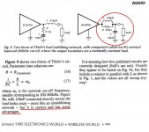
Please, have a look again at fig.1 and fig.2 of my comment on NFDL.
F = 1 / (2 * pi * R * C)
F = 1 / (2 * pi * 800nS) = 200kHz
🙂
Yes....late two beers...and I am working in angular frequency rather than TCs..quite correct!! Just so happens of course that 1.25MHz is ~2PI X 200KHz🙁
Oh well, glad that thats resolved...!
Thank you Edmond for the PGA threads, had not seen that one and also the auto bias, very neat.
Back to the drawing board/spreadsheet...
Regarding your comment that you don't like how the amp sounds, have you had a look at how it recovers from overload? You might be surprised at how often medium power amps clip.
Hi Pete,
Most of the sound quality observations were made at very low level, so its not clipping. It is not a terrible sounding amp, better than something like a 'chip amp' or the Hypex class D, but it is not as good as an AKSA. I suspect that the substitution of a modern fast output stage, CFP driver, has corrupted the transient behaviour. At the time I got it working I did not have a scope. I have built quite a few amps and been involved professionally with a few designs, so a bit critical..!
Most of the sound quality observations were made at very low level, so its not clipping. It is not a terrible sounding amp, better than something like a 'chip amp' or the Hypex class D, but it is not as good as an AKSA. I suspect that the substitution of a modern fast output stage, CFP driver, has corrupted the transient behaviour. At the time I got it working I did not have a scope. I have built quite a few amps and been involved professionally with a few designs, so a bit critical..!
I suspect that the substitution of a modern fast output stage, CFP driver, has corrupted the transient behaviour. !
I didn t dig deeply on mr Cherry s assumptions , but from the few
i did read on the articles that godfrey provided, it seems that the
whole thing stand on adequatly implemented feedback paths.
The frequency response of the feedback paths must be in progression
so the dominant feedback network roll off the frequency response
before the other poles enter significantly in the equation.
Mathematicaly, it looks like classic dominant pole implementation, but using other signal paths for the necessary high frequency negative feedbacks.
Using modern device, the whole calculations are to be remade, as
the frequency response of the modded stages will undoubtly be way
different than the ones in the original design.
Other than that, i ve no idea about the efficency of such a design.
I ll look at simulating the thing to get some clues.
From my recollection of the concept is that it provides no distortion reduction above 20KHz, the assumption being made by Cherry is that most people cannot perceive distortion artifacts above 20 KHz.
That's my major reservation about this kind of design. I'm not comfortable with the assumption that nothing above 20kHz matters.From my recollection of the concept is that it provides no distortion reduction above 20KHz, the assumption being made by Cherry is that most people cannot perceive distortion artifacts above 20 KHz.
While there's no rigorous proof that it does matter, there is a lot of anecdotal evidence and some blind tests that strongly suggest so.
btw To be picky, NDFL does give some distortion reduction above 20kHz, but it falls very fast with increasing frequency.
Hi Wahab,
Yes absolutely, and the individual 'clumps' of gain must themselves be stable. The output stage and the 'VAS inclusive' CDOM will have a major effect and again this is hinted at in the original ETI article, because driver and output transistor substitutions are not advised. For me now I think the whole success of this technique rests on whether it is possible to include the output stage in the last differentiating FB loop. I suspect that it is not..certainly not routinely or reliably...I have tried this on more than one occasion before, with both bipolar and lateral MOS and it is always problematic. If it were, then a successful design would be achieved by selecting Tx and other constants and proceeding as before, recalculating all the TC's to include a more moden faster O/P stage. I'd love to be proved wrong of course!!
Thanks for you thoughts on this!
3. It limits the choice of possible other Zobel networks. For example, it excluded the use of Cherry's preferred one. 😀
From Cherry's articles in Electronics World (Jan 1995 and July 1997), it seems that the load stabilising network in the design posted by Godfrey and Janneman is Cherry's preferred network.
By the way, NDFL is from the seventies, not the eighties as you say on your webpage.
From my recollection of the concept is that it provides no distortion reduction above 20KHz, the assumption being made by Cherry is that most people cannot perceive distortion artifacts above 20 KHz.
Hi Trevor, yes correct, because the recommended roll off in open loop gain is set at 20KHz, however I notice in the ETI amp the frequency break points have been moved up significantly, so that the HF gain is (by my calculation) available up to about 38KHz. Cherry may have arranged this to minimise this failing.
But of course using such a slow output pair, this may well compromise stability.
So far , i made some simulations using the original schematic, safe the
ouput devices which are recent.
It is compared to the same amp with a TMC (traditionnal miller comp),
safe that the miller loop include the output stage , as is the case in this amp.
First result is that there s no difference in THD, wether we use mr Cherry s
compensation networks or a the single classic compensation.
It seems that the dominant pole compensation scheme is the one that dictate
the amplifier global behaviour, and that the influence of the other network is at
best marginal.
Since mr Cherry provided good mathematical explanations about his circuit claims,
one must search where the mistake is.
We can grossly compare the circuit he s proposing to serial low pass filters.
Say that the first filter Fc is set to 1khz, the second to 3khz and the third to 5khz.
Since the first filter Ft is inferior to the following circuits fTs, these latter have nothing
left to be "cut"..
So it goes for the available negative feedback , the dominant pole network will
use all the available loop gain OF ALL STAGES well before the other poles networks enter in function.
At the end of the day, this amplifier rely in fact to high Nfb to reduce distorsion, so
it s no wonder that the classic variant produce exactly the same results..
I wont be radical, though, and i ll check all this a bit lengther in the coming days,as mr Cherry is an university professor, so all that is say has surely some truth as he made valid mathematical demonstrations.
attached are some basic sims.
Attachments
There s an error in the schematic with TMC.
The 68pF compensation cap must go from the output to
the base of Q20 and not to the base of Q3 as displayed in the drawing.
The 68pF compensation cap must go from the output to
the base of Q20 and not to the base of Q3 as displayed in the drawing.
From Cherry's articles in Electronics World (Jan 1995 and July 1997), it seems that the load stabilising network in the design posted by Godfrey and Janneman is Cherry's preferred network.
I was referring to another 'preferred' network 😉, see the snippet below from Cherry's article in EW+WW.
As you see, this Zobel network is incompatible with his peculiar implementation of NDFL.
By the way, NDFL is from the seventies, not the eighties as you say on your webpage.
I guess you were referring to this article "A New Result in Negative Feedback Theory...... (1978 July), right?
Thanks for pointing this out.
Attachments
Tmc
AARGHH....... That acronym was already reserved and it stands for Transitional Miller Compensation.
Don't touch my baby.
...........
It is compared to the same amp with a TMC (traditionnal miller comp),
...........
AARGHH....... That acronym was already reserved and it stands for Transitional Miller Compensation.
Don't touch my baby.
AARGHH....... That acronym was already reserved and it stands for Transitional Miller Compensation.
Don't touch my baby.
Sorry, edmond, but have no fear, my use of this name was
only...transitional!!....
Btw, in a few words, what is exactly your TMC?...
- Home
- Amplifiers
- Solid State
- New Cherry NDFL amp