works for me
"http://www.personal.reading.ac.uk/~shsmchlr/miscfile/CS2007RJMitchell.pdf"
cut from my browser address box
from his page:
Dr Richard Mitchell's Selected Research Papers and Presentations
pretty short, quick ppt style summary - not going to teach anything more than Cherry's papers
"http://www.personal.reading.ac.uk/~shsmchlr/miscfile/CS2007RJMitchell.pdf"
cut from my browser address box
from his page:
Dr Richard Mitchell's Selected Research Papers and Presentations
pretty short, quick ppt style summary - not going to teach anything more than Cherry's papers
OK yes OK many thanks.
I think this guy is the Dr Mitchell who became the worlds first human to have embedded electronics fitted. He was a guinea pig for his own experiment.
Very interesting (and brave) guy.
And a very interesting paper, thank you muchly!
As I work for maxon motors I should appreciate the PID content!!
I think this guy is the Dr Mitchell who became the worlds first human to have embedded electronics fitted. He was a guinea pig for his own experiment.
Very interesting (and brave) guy.
And a very interesting paper, thank you muchly!
As I work for maxon motors I should appreciate the PID content!!
Thank you. On this patent the mentioned German article in ELRAD (post #8) is based.The patent is here: Feedback systems - Patent 4243943
The circuit example in the patent is different to the one published in ETI, though.
Hi All,
First I must apologise in the delay getting back to this, a house and State move are partially to blame!
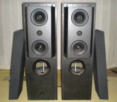
OK, re the sound quality, I have small loudspeakers (Quad 11L), my 'big 'speakers..KEF104.2 didn't make it our hear unfortunately. The rest of the rig is Arcam Alpha 5+ with Tricord clock used as a transport, Burr Brown 1702 based DAC (their top end demo board to be precise one of the few they made that sounded any good!) using 4 X 1702 per channel, and a sophisticated de jitter circuit and a modified Kinshaw Perception pre. Hugh's heard it both with his amps, my amps and the Cherry. By comparision we concluded the Cherry amp is a bit 'flat'...although I suspect we both like tubey, me rather more than Hugh I have to say...!
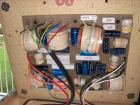
The power supply is 2 X 150VA toroids and around 10,000u per rail, the supply voltage is +/- 37V. The 10,000u is 2X 4700u split with 0.1R. I have tried various permutations of PSU and they make very little difference.
Attached is the circuit, the sim results, THD and loop gain. I hope they are readable this time.
What I did not have when I built this was a 'scope, but subsequently I confirm the amp is stable...thanks Hugh!
However, I also have experience of using the AP Sys 1 and making distortion measurements, having duplicated Doug Selfs results for the 'load invarient'
amp (built on his PCBs) so I know how critical layout earthing etc etc has to be.
Whilst we are on the Doug Self topic, the load invarient amp, despite managing sub 0.0005% ie noise floor THD at 1KHz sounded diabolical on music so I conclude that there are other things going on. I am not of the mind these are magic, I am absolutely sure there are good engineering explainations, but I don't think I am close to uncovering them all!
The sim of the Cherry shows ~0.0001% at 1KHz 40V pk to pk out into 6 ohms, pretty good. This is what very careful circuit design plus a lot of NFB does for you, but I'm not convinced it is 'musical' whatever that means.. 😕
To sum up...I guess I would describe myself as an follower of the engineering school, but without the blinkers worn by some exponents of pure math. Do I believe in magic...alchemy...no! Do I believe sub 0.01% THD+N makes good amp..no not necessarily!!😀
Comments welcome, and you can now see a bit more about me in my profile, sorry for the oversight.
And thanks to Hugh for all the tea, sympathy and coffee!
Cheers
Hallo Jon,
your audible impressions are typicall, if you are compare solid state with tube. Actually you compare in such cases in first line not a transistor amp with tube amp topology. Rather you compare Class AB with pure class A and this is the main reason for "more musical" sonic character. In most cases this will be overlooked. I don't know an amplifier with tubes (not only one), which operates in Class AB.
Regarded the THD values you must check the frequency 100 KHz. If in this case you get still good results, then your described audible deficiencies are as blown away. But this is impossible by idle currents through the output stage arround 20-50 mA (even by p-Spice simulation).
The royal way for you (and in general) it must be the introduce a second amp and the operating in bi-amp topology.
The presently amp for your bass/mid loudspeaker and for the tweeter a single ended (or at least Class-A) amp like ZEN, Aleph or Andrea Ciuffoli's Power follower. Little trouble you will get for callibrate the identical level of both rails without measuring system but with a little audible exercise this is not a real problem.
Check out this threads for more informations, e. g. why I prefer different amplifier topologies for the lower and upper frequency range
http://www.diyaudio.com/forums/soli...-nfb-negative-feedback-me-wrong-question.html
http://www.diyaudio.com/forums/pass...m-results-pass-x-series-us-pat-5376899-a.html
http://www.diyaudio.com/forums/soli...n-single-ended-solid-state-output-stages.html
http://www.diyaudio.com/forums/soli...e-ended-related-solid-state-output-stage.html
http://www.diyaudio.com/forums/pass-labs/147668-aleph-4-simulation-results-circuitmaker.html
http://www.diyaudio.com/forums/pass...zero-o-os-0s-versus-later-aleph-versions.html
http://www.diyaudio.com/forums/solid-state/154073-thd-im-new-approach-perception-distortion.html
By the way, I go to the website of your employer and you are a specialist for motors. Perhaps you can give me recommendations for motors from your home as a replacement for old ones from turntables (record players) and CD players?
Greetings to Melbourne
Andreas
Attachments

Last edited:
Edward Cherry 1983 NDFL amplifier
This is the design published in ETI May 1983.
Each page is a separate JPG, zipped to avoid automatic download in browsers.
The scans came out rather well, I think. Even I can read them!
If I can find the previous issue discussing the principles of NDFL, I'll upload that later too. No promises, though.
Cheers - Godfrey
Attachments
This is the design published in ETI May 1983.
Each page is a separate JPG, zipped to avoid automatic download in browsers.
The scans came out rather well, I think. Even I can read them!
If I can find the previous issue discussing the principles of NDFL, I'll upload that later too. No promises, though. Cheers - Godfrey
Thank you again. This is the original article, which was translated in German and released in the (by post #8) mentioned German magazines "Elrad".
By the way - very good scanning quality.
Means ETI "Electronic Technology Innovations" ?
What about this magazine in general? Are there more interesting articles arround audio electronic?
Last edited:
Means ETI "Electronic Technology Innovations" ?
Attachments

Fantastic, thank you. I will have a good read. As far as I know ETI was Electronics Today International. About the first amp I built (if you discount Sinclair Project 60) was their Audiophile amp circa 1978. At the time it worked well, I gather it was an Australian design. Conventional topology but low global FB and lead compensation. Still have the article for that somewhere if anyone interested.
Motors, please see attached....
Motors, please see attached....
Attachments
Greetings Melbournians, Cheery Fans International etc.
If you want the very earliest published circuit I think you'll find a FET input version in one of the local (Aust') professional journals. It is in the IEEE or something like that. It is from the '70s (1978 maybe) and was a split rail power amp' giving 15 watts into 15 Ohms. It has the NDFL, the bass phase correction cap' and a bias technique that was preset by fixed resistors and did not require adjusting after construction. I.e. the published values gave a very precise value. I have not seen the output triples in quite that form else where. (Bit like some of the JLH Darligton arangements in the 70's from memory I think.)
I'll try and get the exact reference for you but all Uni libraries will hold it in their "stacks" and available to public access. There used to be a completed version of the 15 watt design circuit boards tacked to a notice board in the foyer of the Engineering Building at Monash at one stage. Probably gone now.
His students built 40 plus watt versions of this design.
Cheers, Jonathan (BTW in advance, sorry, I can't spell. No visual memory apparently!)
Last edited:
Okay, got it from the archives.
Cherry.E.M. "A high-quality audio power amplifier" Proceedings of the IREE Australia Vol 39 pp 1-8, Jan/Feb 1978.
Mind numbing maths but also contains practical advice on components.
Cheers. Jonathan
Edit. The Aust' ETI edition (Schematic) of the 45 watt amp (not the 15 watt15 Ohm version) was Jan' 1983 (the 3rd of three parts) Poject No. 488. I understand that people in Sydney (RSC or something like that) who still advertise in the classifieds section of "Silicon Chip" will carry circuit boards for the ETI power amp.
Last edited:
Hi Jonathan,
I tried to post it but >1Mb so rejected. Yes, my friend from Burr Brown suggested that Cherry deliberated "obfuscated" (his word not mine...) the papers so that non academics would not be able to understand it. He did a good job!
Needless to say it is a way of making the system less sensitive to changes in 'plant' and for me this is attractive, because critical parameters such as transient response, distortion performance etc should be nailed down.
And the distortion performance is very good, if we believe the simulator..0.000023% THD at 1KHz and 40V p-p out from 'my' circuit with a few very minor tweaks.
Thanks for the input, if I can help let me know!
Comments on the ETI NDFL 60W design.
Thanks Godfrey for these scans, very interesting and wish I had read it before I embarked on this journey!
This design is obviously based on the Cherry paper I read, so the circuit is very similar to mine, without the elaboration and the values for the constants assumed are close too. One aspect of this amp causes me concern and that is the 'VAS inclusive CDOM ' feedback performed by C8 in the 488 circuit.
This is generally a no no because it promotes chronic instability. However Ed goes out of his way to warn against low ESR power caps and puts 15u+0.15R in the supply rails, so maybe the source impedance at HF is too high to permit oscillation?
I know at the time Ed said that he had been able to do this without any problem.
Obviously if this can be achieved it brings big benefits in terms of high order harmonic reduction. But according to luminaries such as Bob Widlar it is not a reliable technique unless the output stage has a very high fT and my experience bears this out as the capacitor is connected in the 'normal' local to the VAS configuration in my amp, otherwise it is a pig..Comments anyone?
PS question for Jonathan...Cherry.E.M. "A high-quality audio power amplifier" Proceedings of the IREE Australia Vol 39 pp 1-8, Jan/Feb 1978...can you direct me to where you found it? Thanks!!
Last edited:
audiopip, I got it from one of the tertiary institutions in Melb'. I spent the 70's there. Monash would be the closest for you but RMIT Uni in the City may have been the place. If you are really stuck I'll copy mine......but I would have to find it first!!!!
It is unusual and well worth a look. The output triples have a s.signal differential amp in them along with an inductor! The latter may have put off the novice buider
Btw I doubt if he was trying to "obfuscate" or be obtuse in his writing. He was quite agreeable to me chewing his ear one day in the late 70's when I wondered into his lab and I wasn't even doing engineering (Theology actually, which is a field in which one of his brothers lectured in.)
It is just possible that he was genuinely intellectually unpretentious and just assumed people could keep up and so wasn't patronising people by dumbing down his work.
The eventual ETI circuit was preceded by two earlier editions of theory so given that that was a popular magazine with wide distribution he was not averse to making stuff available to the masses.
I think Pioneer in Japan took out a license but I am unsure whether they ever used it.
Btw have you got his two pieces from EW& WW (EW) dated Jan '95 and July '97. Both are titiled "Ironing out distortion" and cover a number of areas in addition to a defense of NDFLs.
I can't find an email address for you. Send me your postal address here and I'll see what I can do.
bright@gil.com.au
Jonathan
Hi Jonathan,
Email address sent to you. Many thanks.
The 'obfuscate' was not my comment, I guess as you say he published his work and wrote several popular articles so that comment is ungrounded. He was polite to me and allowed me to use his work, but I sensed that was about it.
I understand he had a falling out with the audio community over TIM and that probably explains his reluctance to get involved again, that is quite understandable.
Thank you for your help with these papers, I have many of them via the AES but not the more obscure ones.
That's about 100 times better than Cherry's actual measured distortion with his amp. If it's not too much work, perhaps you could modify a copy of your spice model to replicate Cherry's circuit? It would allow an interesting comparison of simulator vs reality.And the distortion performance is very good, if we believe the simulator..0.000023% THD at 1KHz and 40V p-p out from 'my' circuit with a few very minor tweaks.
Even ignoring stability issues, I'm not sure there is much benefit there.One aspect of this amp causes me concern and that is the 'VAS inclusive CDOM ' feedback performed by C8 ...
Obviously if this can be achieved it brings big benefits in terms of high order harmonic reduction...
That kind of output stage (especially with slow output transistors) behaves very badly at high frequencies when driven from a high source impedance.
With the usual Cdom arrangement, the VAS provides low-impedance drive to the output stage at high frequencies, cleaning up it's crossover behavior considerably.
I think I prefer your approach of "getting it right the first time" to Cherry's approach of allowing the output stage to behave like a pig and then trying to clean up the mess with some extra feedback.
OTOH, it's worth bearing in mind that the VAS transistor's Ccb will effectively add some capacitance in the "normal" Cdom position.
A bit off-topic, but that reminds me: every datasheet I've seen for the BD139/BD140 families gives no info about capacitances. Does anybody have any idea what Ccb actually is for these?
Cheers - Godfrey
A bit off-topic, but that reminds me: every datasheet I've seen for the BD139/BD140 families gives no info about capacitances. Does anybody have any idea what Ccb actually is for these?
Cheers - Godfrey
Surely variable from a manufacturer to an other.
Phillips s seems the best with a Ft of 190 and 160 mhz
for the 139 and 140 .
Anyway, a good mean seems about 3.6 and 4.5 pF respectively.
Surely variable from a manufacturer to an other.
Phillips s seems the best with a Ft of 190 and 160 mhz
for the 139 and 140 .
Anyway, a good mean seems about 3.6 and 4.5 pF respectively.
I checked in philips spice models, and it seems
that the values are as high as 30 and 50 pF, although
it s with zero volt across the junction,.
4pF is about normal for small general purpose transistors. BD139/BD140 are fast like small transistors but have much higher power dissipation. They behave almost like 10 small transistors in parallel, so I thought the capacitance must be higher because the die must be bigger.Anyway, a good mean seems about 3.6 and 4.5 pF respectively.
edit: Thank you, Wahab. I missed your last post while I was typing.
So the capacitance is like 10 small transistors, too.
(pats self on head for good guess🙂)
Last edited:
Btw have you got his two pieces from EW& WW (EW) dated Jan '95 and July '97. Both are titiled "Ironing out distortion" and cover a number of areas in addition to a defense of NDFLs.
I can scan them. People interested, drop me an email.
I stupidly drop the first part of Cherry's ETI article in the bin a long time ago, I will be please to get it.
- Home
- Amplifiers
- Solid State
- New Cherry NDFL amp