Are there only this commercial available models A5 and A7 from Pioneer ?
here some URLs to this topic:
What is nested feedback, how it realy works and some examples...
https://linearaudio.nl/sites/linearaudio.net/files/cherry ndfl.pdf
(PDF) Relationships between Noise Shaping and Nested Differentiating Feedback Loops
(PDF) Relationships between Noise Shaping and Nested Differentiating Feedback Loops
Until now I know only this approach under
https://www.linearaudio.nl/sites/linearaudio.net/files/cherry ndfl.pdf
for THD reducing from E. M. Cherry.
But in the attachment there is to find another
https://www.linearaudio.nl/sites/linearaudio.net/files/cherry ndfl.pdf
for THD reducing from E. M. Cherry.
But in the attachment there is to find another
Attachments
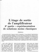

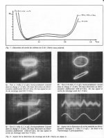

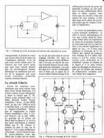
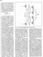

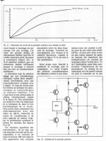
Continuation Audiophile n°37, from 1986
Attachments

Hi Tief, as far as I know Pioneer bought an interest, whether they ever used the circuit I don't know. The fact that Cherry patented this and expected royalties probably put people off. Plus the fact that although this is a way to get more NFB across the audio band, there are other ways of doing this which probably achieve similar results for audio. So pursuing this concept only to get sued was probably a waste of time for many manufacturers. There is some general theory on the web from the university of Reading UK, which shows the concept in a paper on PID theory. So it may have been used in machine/plant control loops, but I have no data on this. Certainly I have not gone any further with it. Cheers!
Very low distorsion can be achieved with other circuitries, but so far NDFL is what get the lowest ratios at the higher end of the audio band.
Not true: error feedback correction performs significantly better.
Not at all, error feedback correction THD is way higher, perhaps that at 1KHz it stand but at 10KHz NDFL is magnitudes below, at the single ppm level.
That being said what is of greater importance is that NDFL designs that linear use three stages, and error correction use the same trick since the error correction is nothing else than inserting a stage gain around the OPS with a local FB loop closed at unity gain.
The original NDFL amp also uses output stage inclusive Miller compensation (BTW, not always stable). Maybe this explains why NDFL (at 10kHz) looks way better than HEC.
Last edited:
That s indeed the case since there s no miracles, and that s the main difference with error correction as partially enclosing the OS with the TIS get more NFB at HF.
I cant give too much indications about stability, but on my tries it was no worse than error correction overall without being more complexe schematically speaking.
I cant give too much indications about stability, but on my tries it was no worse than error correction overall without being more complexe schematically speaking.
It depends on the error feedback scheme you use. Hawksford's arrangement isn't the best application.
On simulations i tested with JVC s error correction (wave correction in their terms) , wich was later also used by Bob Cordell, they claim 20-40 dB distorsion reduction, this can be found in the service manual of their AX 77 (circa 1982) with the relevant part of the schematic displayed with a few explanations.
The amplifier full schematic is quite complexe, btw...
The amplifier full schematic is quite complexe, btw...
output stage inclusive miller compensation and nested negative feedback
Here is the example of utilizing output stage inclusive miller compensation and nested negative feedback.
If you pull out the output stage standalone, the output stage is a current feedback amp by its self. It is configured as unit gain to achieve full bandwidth and high local loop gain.
Also there are only 2 transistors in the Miller loop of output stage. It is stable.
As long as the the outer loop has less unit-loop-gain bandwidth than that of the output stage, overall amp will be stable.
I just did simulation based on the circuit below. Note that the output transistor is not properly biased on purpose, to show the THD. It got 0.003% THD @10Khz, 4Vpp output.
Under any realistic bias current, the THD is not measurable in Multisim software that I am using.
Last edited:
check out from attached PDF (Service Manual Pioneer A-5/A-6 Integrated Amplifier) page 4, 5 and 6.Hi Tief, as far as I know Pioneer bought an interest, whether they ever used the circuit I don't know. The fact that Cherry patented this and expected royalties probably put people off. Plus the fact that although this is a way to get more NFB across the audio band, there are other ways of doing this which probably achieve similar results for audio. So pursuing this concept only to get sued was probably a waste of time for many manufacturers. There is some general theory on the web from the university of Reading UK, which shows the concept in a paper on PID theory. So it may have been used in machine/plant control loops, but I have no data on this. Certainly I have not gone any further with it. Cheers!
The Question is, whether Pioneer also released power amplifiers in those days basically in this topology.
Attachments
Last edited:
- Home
- Amplifiers
- Solid State
- New Cherry NDFL amp