nelson papa, can this work?🙂
Looks neat. However, don't heat pipes work by gravity and need to be vertical?
Last edited:
Hokey Pete... that's serious cooling there!
I can let you use my hammer if you have a fly problem. 😱
How much noise do the 4 (big) fans produce? 😕
The thing is to operate the fans at low rpms. It doesn't take
much air flow to do the job.
😎
you don't need glue
just look at F5 pictures floating around .
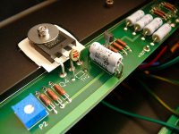
isolate leads of thermistor , and lean it to mosfet case
Yes, you shall not glue them to the MOSFETs. Besides the fact that the glue
probably will melt (and smell funny) the thermistors would react to fast this way. Attached is a photo from an original F5.
BTW the photo shows something interesting, Nelson has chosen to use a lower source resistor value for the n-channel mosfet (0.47 paralell to 2.4 = 0.39)
Attachments
.....
BTW the photo shows something interesting, Nelson has chosen to use a lower source resistor value for the n-channel mosfet (0.47 paralell to 2.4 = 0.39)
old story ; somewhere up in the thread ;
Papa choose their value with sweep & THD meter ;
in any case - he's using some "PING!!" making machine

attaching the thermistor to the drain leg of the FET is one of the fastest ways to monitor temperature changes at the FET junction.you shall not glue them to the MOSFETs. .............. the thermistors would react to fast this way. Attached is a photo from an original F5.
Is the FET Drain and the thermistor touching, or a gap, or glued?
attaching the thermistor to the drain leg of the FET is one of the fastest ways to monitor temperature changes at the FET junction.
Is the FET Drain and the thermistor touching, or a gap, or glued?
Yes it is the fastest way but too fast I believe. I´ve read that people who attached the thermistors directly to the MOSFETs experienced some "overreacting" of
the thermistors, resulting in a bias that goes up and down. From what I see on the photos there is approximatly 3mm air between thermistor and mosfet allowing the thermistor to slowly counteract when temperature rises until a thermal equilibrium is achieved.
I wish I knew servo theory.Yes it is the fastest way but too fast I believe. I´ve read that people who attached the thermistors directly to the MOSFETs experienced some "overreacting" of
the thermistors, resulting in a bias that goes up and down. From what I see on the photos there is approximatly 3mm air between thermistor and mosfet allowing the thermistor to slowly counteract when temperature rises until a thermal equilibrium is achieved.
Your claim that the thermistor is too fast does not seem right to me. Maybe it is applying too much correction.
Creating that gap reduces the level of correction. It might be better to get that intimate contact and reduce the thermistor sensitivity by for example adding a series resistor to the temp comp. There are probably other ways to make the servo effect stable, but reducing the effectiveness of the temperature monitoring does not seem a good way to me with my lack of knowledge.
FWIW when I had the thermistors touching the FETs it took me a really long time to stabilise the bias. I would set it, and ten minutes later would have to dial it back a notch. Ten minutes later I had to dial the other one back a notch. Before I knew it I missed the sweet spot, and I'd have to do it all over again.
I run without thermistors now, and it gets to temperature a little slowly (~2 hours) but once there the bias and offset are rock-solid. I have to readjust every few weeks because of changing ambient temperatures as we approach summer, which the thermistors might have helped me avoid. No free lunch I guess.
I run without thermistors now, and it gets to temperature a little slowly (~2 hours) but once there the bias and offset are rock-solid. I have to readjust every few weeks because of changing ambient temperatures as we approach summer, which the thermistors might have helped me avoid. No free lunch I guess.
I wish I knew servo theory.
Your claim that the thermistor is too fast does not seem right to me. Maybe it is applying too much correction.
Creating that gap reduces the level of correction. It might be better to get that intimate contact and reduce the thermistor sensitivity by for example adding a series resistor to the temp comp. There are probably other ways to make the servo effect stable, but reducing the effectiveness of the temperature monitoring does not seem a good way to me with my lack of knowledge.
"does not seem a good way" - well it has one clear advantage: it works. (This is probably why Nelson has chosen to do it that way).
in the pics, it's not so clear..
does the IRFP240 / IRFP9240 need isolation pads or is it just thermal compound?
-joe
does the IRFP240 / IRFP9240 need isolation pads or is it just thermal compound?
-joe
in the pics, it's not so clear..
does the IRFP240 / IRFP9240 need isolation pads .......
-joe
it needs
ok, ok,
I am somewhat impatient, but I will get it right
Please don't link so huge images, keep em smaller. I have reduced those.

Flip the board over.
Stand up the heatsinks.
Remove the blue plastic from the bottom of the heatsinks.
Now you have 4 towers.
Keep them spaced apart so that there is somewhere for the air to get to...
I'm unsure of what these heatsinks will do in terms of C/w, so you might want to check, NP seems to think they will do well...
I don't like fans... no noise for me...
Heatpipes do not work on gravity, afaik.
what would be great if those heatsinks would actually work using natural convection...
Another idea is to do what is done in broadcast transmitters... pressurize the chassis and then let the air escape across the item needing to be cooled - in this case the 4 heatpipe heatsinks. You might be able to use a much quieter blower, running at lower speed might be a good choice... Ymmv.
_-_-bear
Thats a cool idea, the broadcast thing.
Yeah heatpipes dont care much about gravity, the same as water condenses on all parts of a cool glass in the summer not only at the bottom. Heatpipes USED to have that problem but then they started to put little veins or scribe small lines or use copper mesh on the inside of them as a wick. So they can be sideways. Upside down not a real good idea but rightside up or sideways no problem. I think you can cool the heck out of the mosfets with one tower per.
something to do with the Q5,6?
Maybe this is a silly idea... probably is.
if we're not going to use the current limiting, perhaps we could take the thermistor and have it control the base of Q5,6 then add a capacitor for a time constant? That would slow down the "reaction" time of the thermistor....
while we're at it couldn't Q5,6 be put in place of P1,2 & R3,4, and put the trimmer on the base of Q5,6?
What is that? does it work like a cascode to increase the max Vdc rail voltages, so that the jfets don't get destroyed?
well, wait a second... that's a different amp? 😀
_-_-bear
Or have the thermistor run the fans which was mentioned earlier. Then you really slow down that reaction time.
- Home
- Amplifiers
- Pass Labs
- F5 power amplifier