At last, WE HAVE ROTATION!!!!
Quicktime movie (1.2MB)
OK, so the speed isn't under control and the direction-control logic isn't installed, but it's an important section now operational.
PCB photo and the latest info:
sp10 page6.htm latest events
Quicktime movie (1.2MB)
OK, so the speed isn't under control and the direction-control logic isn't installed, but it's an important section now operational.
PCB photo and the latest info:
sp10 page6.htm latest events
Very encouraging Steerpike....and looks a reasonably easy build. It seems that progress will now be quite fast as you have broken the back of the work.
Have a very good New Year on all fronts,
Brian
Have a very good New Year on all fronts,
Brian
I've finally got the 'missing' ICs I wanted, both TTL and CMOS versions, so I can experiment with both. (Not difficult to source, just the supplier is a long drive away, so I was putting it off till I had a long list)
The 'ideal' transformer is proving tricky to find. This sexy one would be great (sorry USA/Canada/Japan, it's only got a 230v primary) Transformer,multi tapped,pri 230V 50/60Hz,sec 3.2A
But it's fiendishly expensive ($71), so I'm personally going with a 16-0-16 60VA one from another supplier that only cost me $10.00.
The 5V I will just divide off one 16V section, and live with the remote possibility of supply interaction. An option would be to use a totally separate 6V (low-VA = small & cheap) transformer for the logic circuits.
This one below is also 'nice' but it doesn't quite give as much voltage as desired - meaning the motor starting torque would be somewhat reduced. Maybe no problem for most users.
Transformer,encapsulated,45VA,pri 2x0-115V,50/60Hz,sec 1x0-9V 2x0-14V
I've only looked at suppliers within driving distance of home, so elsewhere in the world you may find a perfect match easily.
How is it coming on Steerpike?
Funny you should ask: 30 seconds before I read your post, I uploaded the new PWM generator circuit I've been working on.
The original circuit I posted here came direct from the Philips 1988 IC Databook but on calculating values for it earlier today, I'm pretty sure it would never work as published. My modified version is down the bottom of <<page4>>.
The power amplifier stage is now complete - a picture here on the bottom of <<page6>>.
The transformer I bought a couple of weeks ago that was supposedly 16V, turns out to be a 12V component! Way too much effort to go all the way back and complain - it can sit around & be used in another project.
Last edited:
Funny you should ask: 30 seconds before I read your post, I uploaded the new PWM generator circuit I've been working on.
The original circuit I posted here came direct from the Philips 1988 IC Databook but on calculating values for it earlier today, I'm pretty sure it would never work as published. My modified version is down the bottom of <<page4>>.
The power amplifier stage is now complete - a picture here on the bottom of <<page6>>.
The transformer I bought a couple of weeks ago that was supposedly 16V, turns out to be a 12V component! Way too much effort to go all the way back and complain - it can sit around & be used in another project.
Well - there you go! Irish mind reading again. It just happens that I dug out my PS. tonight and poked around a bit to see if I could source the problem. No luck of course!
I can feel were getting closer to having something to build...thanks for the hard work Steerpike.
Looking forward to future posts.
Rick
Looking forward to future posts.
Rick
It just happens that I dug out my PS. tonight and poked around a bit to see if I could source the problem. No luck of course!
What is it doing or NOT doing ?
What is it doing or NOT doing ?
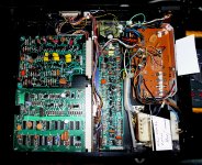
It simply died. No noise, smoke, fumes, heat. New electrolytics were fitted 3 years earlier. Regs seem to be normal, Diodes all work. But voltages unstable in the 32.5 section. They swing widly, yet as I said, regs appear to test OK and caps also.
It was working and then simply died without fuss or warning. This as you can see below is an off-plate/remote PS adaption.
Attachments
Last edited:
It simply died. No noise, smoke, fumes, heat. New electrolytics were fitted 3 years earlier. Regs seem to be normal, Diodes all work. But voltages unstable in the 32.5 section. They swing widly, yet as I said, regs appear to test OK and caps also.
That's sort of a contradiction. If the regs are working OK, the voltage can't swing wildly. Unless the drive circuitry is drawing a phenomenal current - but something must then get hot.
Does it ever exceed 32V, or always dip below 32V?
Does the Ac voltage entering the rectifier for that section remain fairly stable - should be around 25V AC I believe?
Thanks Steerpike,
I have decided to wait until your units are ready.🙂
I am sending the deck + PS etc to vantage audio who are the very good UK specialists in classic DDs. It will be handy to have an overhauled PS + motor. [I have a second SP-10 Mk11P just as it came from a BBC studio. It will be simple to add the old supply to this to compare with yours!!😉 ]
A local tech has seen this PS and has no clue, but I think that he is more fitted to dealing with stage amps etc.🙄
Here is Vantage Audio's site:
VANTAGEaudio reference systems® from GRP Associates
The original circuit I posted here came direct from the Philips 1988 IC Databook but on calculating values for it earlier today, I'm pretty sure it would never work as published. My modified version is down the bottom of <<page4>>.
This has been RE-modified. I cannot get anything useful out of the Philips circuit. I abandoned it and am going with a voltage-to-current PWM setup.
pulsegen.gif...and am going with a voltage-to-current PWM setup.
I'm liking this circuit a lot! Varying the reference voltage (IC2 pin 3) gives a variable PWM ratio of around 7,5x. This is adequate for speed control over the entire range of 14RPM up to 100RPM. BUT, it's pushing the stability limits of the current source at the extremes. My prefered solution is to select a different value of R16 for each speed, use R4 only as a fixed reference, and drive Ic1B's pin 11 (Control Voltage) with the servo/feedback error signal. Since the CV pin modifies the reference point of the 555's internal comparators, it provides a very linear means of PWM control.
(my breadboard power supply has decided to go on the blink this weekend. The Fates must have pms)
Last edited:
Just checking if there are any updates, as I'm sure like others, I look foreward to the fruits of your work...I'm really looking forward to getting some new electronics into my SP10's...
Rick
Rick
I've got the PWM drive circuit going and generating nice variable duty cycle waves. (the dead power supply had put a delay on things, but that is now repaired).
Basically what I now have is the DD equivalent of a commutated DC motor driven from a variable voltage power supply. So it is ready for some servo control experimentation.
Basically what I now have is the DD equivalent of a commutated DC motor driven from a variable voltage power supply. So it is ready for some servo control experimentation.
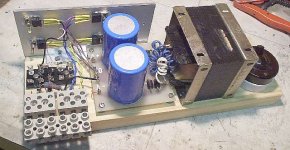
My under-currented Heathkit testbench supply and an overly bulky and under-voltaged computer power supply have been thus far an annoying pair with which I have been doing my testing.
I decided I needed something more convenient to do the SP10 experiments with, so I put this together with parts lying around. It's not a great supply, but it will make things from now on less frustrating!
I decided I needed something more convenient to do the SP10 experiments with, so I put this together with parts lying around. It's not a great supply, but it will make things from now on less frustrating!
Attachments
The circuit for the phase detector and PWM generation is up:
Phase/frequency detector
I'll be doing the PCB layout for this part in the next few days. This particular phase detector layout I have not experimented with pratically before, so it will be interesting to see what sorts of results it produces!
I have left the quartz oscillator out so far. Without any pitch control, it is a very simple circuit addition - I think I'll make space for it on the PCB in that form.
Variable pitch will require the intervention of a microprocessor, which isn't yet on the cards - not until the speed control loop is working on its own.
A few minor corrections to the circuit...
clickable link to PFD circuit
The PCB layout is progressing quite fast.
clickable link to PFD circuit
The PCB layout is progressing quite fast.
The PCB layout is now done too. Slightly messy still, it needs to be checked and tidied up a bit. The clock reference (crystal) is not on this board - for testing I will use an external oscillator so I can apply continuously variable frequency.
click: image of PCB layout for PLL
click: image of PCB layout for PLL
- Home
- Source & Line
- Analogue Source
- New Technics SP10 motor controller specification