Hmm......either something isn't adding up, or I'm not using PSUDII correctly.
One thing that's a little unusual is the 413V offload voltage for the Edcor; that's 15% regulation. I would have guessed it to be better than that.
If I input 413V offload V, 40.3R secondary R, 120V primary, 1.2R primary R into the transformer properties box, PSUD is giving me a transformer with 413V/54.5R, which easily gets 500+ volts B+ if we want it, although I'm not sure I believe the numbers.
Using 360V/54.5R transformer properties barely makes 450V depending on choke R, and using 360V/40.3R yields a B+ of 458V with the same choke as above. Both of the above are with CLC=47u-10H/63R-330u.
Simulation software has improved considerably, over time. Even as good as it is, PSUD2 only gets you close. You have to build it and then measure. Good old cut and try is still (IMO) the method of choice. PSUD2 is definitely good for reducing the number of iterations necessary to achieve a particular goal.
The secondary DCR is a wildcard when you don't have the iron in-hand to measure it. I usually get within 10-20% with PSUD, depending how accurate my transformer/choke DCR numbers are. The ripple values are similar, again depending on how accurate ESR numbers you have.
When split between two iron choices, go for the one that gives you more B+. It's easy to burn off a little B+ with some extra series R next to the choke. That is, of course, if you are not looking at Hammond iron. Hammonds run hot...pretty much any time I have tried them in the past few years. You will get 20% or more B+ than you expected. Same for Allied (which are made my Hammond).
When split between two iron choices, go for the one that gives you more B+. It's easy to burn off a little B+ with some extra series R next to the choke. That is, of course, if you are not looking at Hammond iron. Hammonds run hot...pretty much any time I have tried them in the past few years. You will get 20% or more B+ than you expected. Same for Allied (which are made my Hammond).
boy wonder. That was a xpwr033. 760Vct. (380-0-380). I used it to get the secondary winding (dcr)impedance, which would be close to the xpwr0002. I couldn't see what you had in your sims. After measuring it I used 39ohm in my sims since it has a few less turns. I thought you wanted the voltage measurements to calculate edcors regulation.
I think you will find that a 10H choke will measure a little higher DCR.
When we are absolutley sure that 465 B+ is what we want to get the desired results, I will probably place an order with EDCOR so it will be available to everyone without the design charge. That is unless we get enough people to want the same one and then maybe they will wave the $40 charge.
The xpwr0033 would be a good tranny if it had a bias winding.
Last edited:
Eli,
For mostly personal reasons, how many more volts does the B+ need to be in order for the ltp to function correctly?
With 465VB+ we are dangerously close to, if not above 500V no load. While DIY, they do make a mess when they go pop. This is especially true as rknize pointed out with hammond iron.
The Edcors I have also run a little hotter than design, but certainly not 20%.
It may be wise to consider motor run or using el's in series anyway. It wouldn' bother me one bit to see the voltage up closer to 500V
Last edited:
The xpwr0033 would be a good tranny if it had a bias winding.
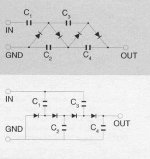
The 5 VAC rectifier filament winding can be voltage multiplied to get the bias rail. 10 stages along the lines of the 2nd schematic in the uploaded graphic ("ripped" from VMI) should prove satisfactory.
The diodes in that 1/2 wave parallel topology are under equal stress. 1 A./20 PIV 1N5817 Schottky diodes, at 12 cents each from Mouser, will work well.
The voltage stress on the caps. in the multiplier increase, with each successive stage. Bias supply draw is never more than a few mA. Perhaps as little as 33 μF./stage is all that's needed.
Attachments
Eli,
This may not sound right so please forgive my newbieness. In the above post relating to using the FET follower, I am assuming that the signal is taken from the FET source and then cap coupled to the kt88 grid. The kt88 bias is then applied after the capacitor.
I don't think the following adds another pole either and may kill two birds with one stone. I can't claim that I am smart enough to come up with this on my own, I took it from Georges TublabSE.
I hope I didn't get the drain and source of the FET backwards I am not at a place where I can check. ( i think the drain goes to +)
Using your idea as the basis, if we cap couple the t7 to the gate of the FET and then dropped the source to the neg bias rail across the 66kRs (only for example) we could then bias the FET with a voltage divider from the bias rail. The kt88 grid would be direct coupled to the FET. The FET source voltage would set the kt88 bias. The drive source impedance for the kt88 would be determined by the FET Source resistance(Rs). The impedance that the ltp sees would be determined by the voltage divider resistance.
I don't know if it is useful here but this would also allow us to drive the kt88 into A2 operation. If a2 is relavent in UL PP design it certainly would help differentiate this amp from the run of the mill ones.
Take a look at george's site under tubelab SE schematics. (not the simple SE)
Last edited:
Eli,
This may not sound right so please forgive my newbieness. In the above post relating to using the FET follower, I am assuming that the signal is taken from the FET source and then cap coupled to the kt88 grid. The kt88 bias is then applied after the capacitor.
I don't think the following adds another pole either and may kill two birds with one stone. I can't claim that I am smart enough to come up with this on my own, I took it from Georges TublabSE.
I hope I didn't get the drain and source of the FET backwards I am not at a place where I can check. ( i think the drain goes to +)
Using your idea as the basis, if we cap couple the t7 to the gate of the FET and then dropped the source to the neg bias rail across the 66kRs (only for example) we could then bias the FET with a voltage divider from the bias rail. The kt88 grid would be direct coupled to the FET. The FET source voltage would set the kt88 bias. The source impedance would be determined by the FET Source resistance(Rs). The impedance that the ltp sees would be determined by the voltage divider resistance. I don't know if it is useful here but this would also allow us to drive the kt88 into A2 operation. Take a look at george's site under tubelab SE schematics. (not the simple SE)
When you DC couple the FET to the O/P tube's control grid you have the option of entering a positive grid current regime. Some tube's can work that way and some can. The KT88 is rated for positive g1 current. So far, so good. The fly in the ointment is the PSU complexity needed. OTOH, when you DC couple the FET to the splitter plate and cap. couple the FET to the "final", PSU complexity need not increase. However, you can't enter a positive control grid current regime. Either way, you have to accept trade offs. Once more, TANSTAAFL rules.
I strongly suggest DC coupling to the splitter, as doing so retains the fundamentals of the design we've been considering and it's easily executed.
To get an improved understanding about the utility of FETs in tube circuits, read Keen's MOSFET Follies and Tubelab's "PowerDrive".
BTW, the IRFBC20 I mentioned is a good candidate, given its low and stable reverse transfer capacitance. Any device with a large reverse transfer capacitance makes a POOR voltage follower, as said capacitance shunts HF info. to AC ground. 🙁
Anyone here have a HP 339a? I bought one as part of the test equipment I picked up for this build. I posted in the Equipment forum, but it doesn't get much traffic. Could a kind soul look over my post there and get me on track?
Now, back to the Monoblocks!
Now, back to the Monoblocks!
Last edited:
The secondary DCR is a wildcard when you don't have the iron in-hand to measure it.
Exactly. Does anybody know if the Edcors tend to run a little hot on the output V?
SGregory: sorry about that, the 380V vs 360V explains the regulation confusion.
It looks like your XPWR0033 has about 9% regulation, which is reasonable.
So, for the Ecdor XPWR002 inputting 9% regulation, 360V, 220ma into PSUD transformer properties box gives an R of 32.4 ohms.
The original design uses a guess of 31R....so, should be close enough. Also, since we are not going to be pulling 220ma, the voltage will be a bit higher, which can be adjusted once built with different values of C1.
If you want to later experiment with 500+V B+, then more transformer volts will be needed.
Caps go pop
The Panasonic TS-UP's spec'd are reasonably low ESR, and are available in 500V rating, with a 550V surge rating. That avoids stacking caps and R's, although there is no reason (except perhaps available real estate under the hood) that you couldn't use series caps.
I'm using them presently in an amp with a 360V winding, so far, so good. They are seeing close to 507V when starting from cold.
I am also very interested in the FET coupling (powerdrive etc) of the finals, but it may be outside of the scope of this thread. I suppose it depends on how far the gang here wants to deviate from the basic Mullard design. Lose the coupling cap, no blocking distortion, etc. I suppose if Mullard had them in 1955, they would have used em'.😉
Eli,
With 465VB+ we are dangerously close to, if not above 500V no load. While DIY, they do make a mess when they go pop. This is especially true as rknize pointed out with hammond iron.
The Edcors I have also run a little hotter than design, but certainly not 20%.
It may be wise to consider motor run or using el's in series anyway. It wouldn' bother me one bit to see the voltage up closer to 500V
The Panasonic TS-UP's spec'd are reasonably low ESR, and are available in 500V rating, with a 550V surge rating. That avoids stacking caps and R's, although there is no reason (except perhaps available real estate under the hood) that you couldn't use series caps.
I'm using them presently in an amp with a 360V winding, so far, so good. They are seeing close to 507V when starting from cold.
I am also very interested in the FET coupling (powerdrive etc) of the finals, but it may be outside of the scope of this thread. I suppose it depends on how far the gang here wants to deviate from the basic Mullard design. Lose the coupling cap, no blocking distortion, etc. I suppose if Mullard had them in 1955, they would have used em'.😉
Last edited:
Eli,
For mostly personal reasons, how many more volts does the B+ need to be in order for the ltp to function correctly?
With 465VB+ we are dangerously close to, if not above 500V no load. While DIY, they do make a mess when they go pop. This is especially true as rknize pointed out with hammond iron.
The Edcors I have also run a little hotter than design, but certainly not 20%.
It may be wise to consider motor run or using el's in series anyway. It wouldn' bother me one bit to see the voltage up closer to 500V
First, 500 WVDC 'lytics can take a brief surge above rating, at turn on. Of course, that's good news.
The problem with the LTP is a net load that's too small. Increasing the LTP anode resistors will raise the net load upwards. The B+ rail voltage needed to support such an action would blow the KT88s out of the water. 🙁
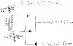
Pete Millett, clever fellow he, has provided us with a means of squeezing 2 B+ rails, 1 approx. 2X the other, out of a single CT rectifier winding. Please refer to the uploaded graphic. That technique could provide a "tall"/low current rail to power the small signal tubes and a "short"/high current rail to power the KT88s. Large LTP anode resistances are now OK, but watch out for the dissipated heat.
As mentioned previously, TANSTAAFL always bites you on the bottom. All "improvements" carry a price tag.
Oh yeah, for a number of reasons, a vacuum rectifier, would be ideal connected to the "tall" rail filter.
Attachments
TANSTAAFL? Probably close or similar to the meaning of the acronym ASSUME.
I ask this out of curiosity. What would happen if we moved the CCS in the ltp to the anode? Would need two of course. The common cathode would then return to a resistor.
I ask this out of curiosity. What would happen if we moved the CCS in the ltp to the anode? Would need two of course. The common cathode would then return to a resistor.
TANSTAAFL? Probably close or similar to the meaning of the acronym ASSUME.
TANSTAAFL = there aint no such thing as a free lunch
I ask this out of curiosity. What would happen if we moved the CCS in the ltp to the anode? Would need two of course. The common cathode would then return to a resistor.
No go! The tail is THE place for a CCS. The tail CCS forces symmetry between the 2 sides of the diff. amp. When a side goes up, the other side must go down and vice versa.
Look for SY's recent thread on this subject. He went so far as to put dissimilar triodes into a LTP, with a tail CCS, and balance was still maintained. 😀
Exactly. Does anybody know if the Edcors tend to run a little hot on the output V?
Both of mine were *right* on under load (XPWR035 and XPWR131). Regulation is pretty good.
Thanks for explaining your acronym. I did read SY's thread but 90% went over my head. I caught the forced symetry bit, but was thinking that by tweeking the ccs of the bottom(right hand) triode one could obtain symmetry. Just a mental excersize.
Can we make an LTP work Mullard style without going to extreme voltages. If not I am in on the FET as a way to improve the design.
The PS design complexity shouldn't be too much of an issue. There are several ways to skin the cat here, but I prefer the K.I.S.S. method of having the appropriate windings. It is simpler, and easier for people like myself to follow. More importantly in 5yrs I can trouble shoot it. At least with EDCOR if a new design is purchased it becomes available to everyone. It should not be an expensive tranny either, probably the same price as a XPWR002 I'm guessing. Cheaper yet if we eliminate the filament windings on the core.
boywonder, Of the 4 EDCOR PT's I own, non were less than the rated voltage. They were not hot enough to require any adjustments however.
My simpleSE's were spot on, my tubelabSE is 370V on a design of 365V.
FYI I have 4 matched GEC kt88's and a matched ef806SG (ef86) pair on their way from McShane. I hope the GEC's are worth it. Even though I have the ef86's on their way doesn't mean I will use them.
The PS design complexity shouldn't be too much of an issue. There are several ways to skin the cat here, but I prefer the K.I.S.S. method of having the appropriate windings. It is simpler, and easier for people like myself to follow. More importantly in 5yrs I can trouble shoot it. At least with EDCOR if a new design is purchased it becomes available to everyone. It should not be an expensive tranny either, probably the same price as a XPWR002 I'm guessing. Cheaper yet if we eliminate the filament windings on the core.
Bumping the secondary to 370 or 380 volts will certainly allow some headroom for different chokes, higher B+, and we can dial in the B+ with C1. Perhaps a custom much like the XPWR033 with a bias tap instead of the 5V winding. I also like the idea of losing the filament winding since it gives the option of start-up delay, human-powered or otherwise. It also gets the filament noise out of the B+ transformer. I'm not planning on building this anytime soon so it really doesn't matter what I like.😱
I guess it somewhat comes down to budget...
$ option
Off-the-shelf transformer (Edcor or boosted Antek), and use the filament winding. Hammond open frame 15X series choke. Very straightforward. Somewhat limited higher B+ possibilities (at least with the Edcor XPWR002)
$1/2 option
Custom transformer with filament and bias windings. Very straightforward. Flexible B+ options.
$$ option
Custom transformer, separate filament transformer. Hammond 193 series enclosed choke, etc. on-delay (if desired), More flexibility.
I called Edcor recently about a custom and they were quoting 5 weeks so we should probably dial this in so orders can be placed.
Last edited:
I don't know if this has been mentioned, but there is also the Hammond 700 series. The 710 would fit the bill. I've used both the 712 and the 715 before. The 715 were fine. The 712 (bought years later) ran hot but were OK.
For whatever my opinion is worth, I'm greatly in favour of keeping it simple. i.e. using an appropriate power transformer, over using hacks to overcome the challenges. The same goes for B+ levels. I have no problem with series caps in the power supply though if the rail is too high for 500V caps.
Having said all that, I don't understand all the challenges, so I won't be critical about any directions this goes, as long as it doesn't stray for the sake of creativity over simplicity (simplicity for future DIY builders that is).
..Todd
Having said all that, I don't understand all the challenges, so I won't be critical about any directions this goes, as long as it doesn't stray for the sake of creativity over simplicity (simplicity for future DIY builders that is).
..Todd
hey-Hey!!!,
The PSUDii inputs for iron DCR will matter more in a cap-input filter than for a choke-input filter. The higher rms current created by the charging spikes is to blame. If y'all feel like messing around, model a PS with an L-C filter and one with a C-L-C filter. As the first C increases in size the voltage delivered goes up, but the impact of the DCR gets larger. The nearly constant current delivered into an L-C filter cares much less about the DCR...try increasing the choke or power TX's DCR and see...🙂
cheers,
Douglas
For whatever my opinion is worth, I'm greatly in favour of keeping it simple. i.e. using an appropriate power transformer, over using hacks to overcome the challenges. The same goes for B+ levels. I have no problem with series caps in the power supply though if the rail is too high for 500V caps.
Having said all that, I don't understand all the challenges, so I won't be critical about any directions this goes, as long as it doesn't stray for the sake of creativity over simplicity (simplicity for future DIY builders that is).
..Todd
I agree, lets keep it simple and only make needed changes. The thread is dangerously close to spinning out of control.🙂
I like the existing supply. What is the max B+ possible with only value tweeks?
Or
With a custom uprated transformer, but staying with the existing 500V rated caps?
Last edited:
- Home
- Amplifiers
- Tubes / Valves
- Mullard 5-20 KT88 PP blocks!