You can ask Richard if he have surplus stock. I ordered from him two 300va 22-22 for 40$ each about two month ago. Check also for Antek, for more competitive price.
He had 1 left for $40 so I ordered it. They would be $95 + tax and shipping. They are built per order even if it's just one, so that may explain if it's a little pricey.
He had 1 left for $40 so I ordered it. They would be $95 + tax and shipping. They are built per order even if it's just one, so that may explain if it's a little pricey.
Don't forget to test it. It is rated at 22v but when I test mine I got 24v.
Don't forget to test it. It is rated at 22v but when I test mine I got 24v.
That is caused by regulation margin (transformers are rated at full load) and by variations of AC from a wall which sometimes can be another 6-8%
Hi Peter;
I got the kit the other day, thanks for the fast delivery. I have a question regarding running each board in bridged mode as my speakers are 8ohm. I have the toroid mentioned above (got it yesterday). So i use one rectifier board to drive both boards run in bridged mode...correct? So i will be using R0 and which IN/OUT do I use?
Regards,
Wayne
Yes, one rectifier board.
The bridged configuration has been explained here: http://www.diyaudio.com/forums/audi...chip-amp-kits-dacs-chassis-13.html#post636565
You'll be using R0 and and both IN and OUT connections as you need both positive and negative inputs/outputs. You will also need SG (signal ground) but no OG connection.
Bridged setup can be compared to both amps connected in series, where you feed each amp section with opposite polarity signal and the output is taken from "between" the amps with no reference to ground. Read page 7 of this manual for more info: http://www.firstwatt.com/downloads/f4_om.pdf
Sorry for these basic questions. Looking at the LM4780 bridged schematic from Nationals site. The input positive is split between the inputs and uses common signal ground. The output from each (3886) is put across the speaker, thus like you said no 'OG' ....correct?
Which output goes to which lead on the speaker?
Thanks for your help!
Which output goes to which lead on the speaker?
Thanks for your help!
National's bridged schematic is different from mine; with their setup you can connect unbalanced source and still get balanced output.
With my kit, to get balanced output, you need to connect balanced input.
The + from a speaker is connected on a same side where positive input (of a balanced signal) is hooked up..
To use unbalanced signal with this bridged amp you can simply use an input transformer: http://www.diyaudio.com/forums/audi...kit-building-instructions-22.html#post1712724
So, if I run it in stereo or parallel I can used unbalanced inputs? I know parallel is recommended for 4ohm speakers but can it be run this way with an 8ohm load? That was my only reason for using bridged mode is my speakers are 8ohms.
Ok I know this is a long way back in the thread but the volume pot with 8 pins on the square pot. Are all pots of this type wired the same.. I have a ALPS pot i got from a dead amp rated at 60k x 2. Would it be wired the same?
So, if I run it in stereo or parallel I can used unbalanced inputs? I know parallel is recommended for 4ohm speakers but can it be run this way with an 8ohm load? That was my only reason for using bridged mode is my speakers are 8ohms.
Yes, unblanaced signal is fine with stereo or parallel configuration. Also, 8hm load is perfectly fine here, as it's easier to drive.
Peter, thank you for your patience. Hopefully this will be my last question regarding this.
If running in parallel:
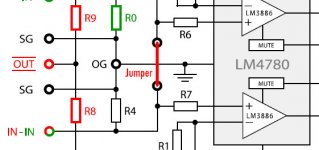
1) install jumper, R8, and R9
2)Regarding inputs. Being there is now a jumper, do I use just the Red IN and associated SG or do I split the positive side between both IN's and SG between both SG's?
3)Red OUT goes to + side of speaker and OG to - side of speaker?
If running in parallel:
1) install jumper, R8, and R9
2)Regarding inputs. Being there is now a jumper, do I use just the Red IN and associated SG or do I split the positive side between both IN's and SG between both SG's?
3)Red OUT goes to + side of speaker and OG to - side of speaker?
Hello, I've been reading this thread as well as this tutorial and can't seem to figure out what to solder to what.
Right now I have both reds soldered together and both blacks solders together as well. I don't want to risk damaging these transformers so if someone could clarify this for me please it would be greatly appreciated.
Here is a picture.
Right now I have both reds soldered together and both blacks solders together as well. I don't want to risk damaging these transformers so if someone could clarify this for me please it would be greatly appreciated.
Here is a picture.
An externally hosted image should be here but it was not working when we last tested it.
That transformer wont work. You have 22V secondary and 220V secondary. Wont work. If you had 22V and 22V that would be fine and you would tie the middle blue/green together to get a 0V for power ground.
Uriah
Uriah
Here is a picture.
An externally hosted image should be here but it was not working when we last tested it.
Are you sure it's not a typo? Such secondaries configuration is rather strange.
Don't tie secondaries together but use them separately with my kits.
Anyway, connect primaries in parallel (reds together and blacks together) and measure secondaries first.
- Home
- More Vendors...
- Audio Sector
- Commercial Gainclone kit- building instructions