syn08 agrees with you John, this design is unconditionally unstable 🙂
Which sim analysis did you run that showed unconditional oscillation? Transient? Phase margin?
Which sim analysis did you run that showed unconditional oscillation? Transient? Phase margin?
AFAIK, there is a certain tradeoff between between regulation and stability between the Salas and Ikoshunt
I think I'd settle for stable with -125db @ 20KHz ripple rejection but I've been known for my low standards. 😉
It's in the breeze for me as I wouldn't use either reg but I'm intrigued as to why Iko's won't operate as proposed for me whereas Salas' will. 😕
Sure, unconditional stability is nice and all but it's not the only option. Applications are situational.
Why not post your simulation schematic?
- keantoken
Why not post your simulation schematic?
- keantoken
syn08 agrees with you John, this design is unconditionally unstable 🙂
Which sim analysis did you run that showed unconditional oscillation? Transient? Phase margin?
I'm not saying the circuit is unstable in reality, just in my simulation. I haven't built it.
Multisims interface is a bit more interactive than LT4 and after you've captured the circuit, you can "run" it and monitor it's operation in "real time". Real time operation shows oscillation - that's as far as I went (can go actually).
Sure, unconditional stability is nice and all but it's not the only option. Applications are situational.
Why not post your simulation schematic?
- keantoken
Maybe I'm odd but I think that first and foremost a circuit should be stable. When you meet that option then you can think about other things.
🙂
I definitely want this regulator stable. Otherwise the show stops right there. And I do know that phase margin analysis predicts instability. I've done this long ago, it's a longer story. I arrived at the current stable circuit not by chance. Other people built it too, and in reality is stable.
However, there are ways to make the phase margin larger. Add a 5pF to Q3 and Q2 and see what happens. Another thing you can do, an idea from Salas, who used this trick before, is to add a 1R resistor in series with the output cap.
The reason I did not try to compensate is because I built it in reality, several times, and it was stable.
I'm not saying the circuit is unstable in reality, just in my simulation. I haven't built it.
Multisims interface is a bit more interactive than LT4 and after you've captured the circuit, you can "run" it and monitor it's operation in "real time". Real time operation shows oscillation - that's as far as I went (can go actually).
John, sorry if I came across as dismissive, I was a bit in a hurry last night.
The multisim run sounds like transient analysis, which, in my experience with simulators versus reality, has been the best predictor of regulator stability/instability. This in comparison with calculating the phase margin. I don't know if you have set these parameters, but in ltspice the closest analysis to something real is transient, with the settings "skip initial operating point" and "start all voltage sources form 0." Sometimes when I really want to see what's going on I sim the rest of the psu as well, rectifier bridge, filter, etc. Even though it's still not reality, it can be a good indicator of what may happen in the real circuit.
Now, there are some details which are important about the simulation. For instance I always use parasitic properties for all caps. Sometimes I introduce wire parasitic properties, all, of course, in relation with a certain layout. Sometimes I exaggerate the parasitics to emulate a lousy build. It's all part of my test before I hit the iron, or sometimes when I see some unexpected behaviour in the real circuit. Lot of time put into this. As I got more experienced I can sort of get a feeling from some of the simulations and dismiss the mods right away. My experience with the simulator is that in way do I interpret the sim result literally. To me the simulator is a tool, and I do my best to read between the lines as far as the result is concerned.
Back to this design. Stability is the first target, as you say, and I agree with you. Nothing else matters if the regulator is oscillating. In fact that's not a regulator any more 🙂 But always keep in mind the gap between simulation and reality. I can give you the ltspice file (I don't have multisim) and all necessary models if you'd like it.
Maybe I'm odd but I think that first and foremost a circuit should be stable. When you meet that option then you can think about other things.
🙂
Yes, stable under normal conditions. While salas v1 reg was stable unconditionally. I think the first is sufficient for me.
Yes, stable under normal conditions. While salas v1 reg was stable unconditionally. I think the first is sufficient for me.
I guess I should add something about the tests I've done on the real circuit. First, I built it several times, using various makes capacitors. This allows for some build variation. Also, I built it a few time on a pcb, and a also as parts in the air, meaning each part soldered to parts near by. An air sculpture of sorts. On purpose I have been a bit careless about length of wires for sensing or output. I would not call these normal conditions, but I like to do that, so to see how the circuit behaves. Then, once powered up, I tested it for various input and output voltages (5V, 12V, 15V, 22V, 24V, 28V, etc.). With passive load (resistor) and active load (power mosfet) for various currents, 50mA, 200mA, 300mA, 500mA, 1A, 2A, 3A. The mosfet active load was set usually to some DC current and then I applied to its gate a square wave or a sine wave to get an AC current component on the output. With all these tests it did not oscillate. When all tests were passed, I felt confident that it would be stable. I cannot be 100% confident that under all imaginable conditions it will not oscillate. But 100% confidence isn't what I want anyway.
Now, this being said, I have revision 5f in the pipe line, with a phase margin of over 80 degrees. If that is not, in theory, unconditional stability, I don't know what is. But I haven't built it yet, and it will be some time before I can do all the tests and make it public.
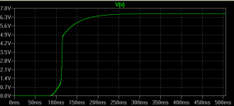
For example, this is how my transient analysis looks like on revision 5d.
Voltage in: 40V
Voltage out: about 6.45V
Current Limit: about 300mA
Active load: PULSE(100m 125m 0 5u 5u 20u 40u)
which is a square wave jumping from 100mA to 125mA, rise and fall times 5uS
Voltage in: 40V
Voltage out: about 6.45V
Current Limit: about 300mA
Active load: PULSE(100m 125m 0 5u 5u 20u 40u)
which is a square wave jumping from 100mA to 125mA, rise and fall times 5uS
Attachments
John, sorry if I came across as dismissive...
... and all necessary models if you'd like it.
Hi Iko,
I didn't feel any sting 😀
If you could post the models for the MOSFETS you've used, that would be a start.
Multisim came with this for the IRFBC40:
.SUBCKT IRFBC40 1 2 3
* Model generated on Sep 8, 97
* MODEL FORMAT: SPICE3
* Symmetry POWER MOS Model (Version 1.0)
* External Node Designations
* Node 1 -> Drain
* Node 2 -> Gate
* Node 3 -> Source
M1 9 7 8 8 MM L=100u W=100u
* Default values used in MM:
* The voltage-dependent capacitances are
* not included. Other default values are:
* RS=0 RD=0 LD=0 CBD=0 CBS=0 CGBO=0
.MODEL MM NMOS LEVEL=1 IS=1e-32
+VTO=3.8654 LAMBDA=0.000859403 KP=5.70304
+CGSO=1.3132e-05 CGDO=1e-11
RS 8 3 0.0001
D1 3 1 MD
.MODEL MD D IS=1.80835e-09 RS=0.0143656 N=1.37083 BV=600
+IBV=10 EG=1 XTI=1 TT=2.57052e-06
+CJO=3.03085e-09 VJ=0.500619 M=0.897448 FC=0.5
RDS 3 1 1e+07
RD 9 1 1.08045
RG 2 7 1.28518
D2 4 5 MD1
* Default values used in MD1:
* RS=0 EG=1.11 XTI=3.0 TT=0
* BV=infinite IBV=1mA
.MODEL MD1 D IS=1e-32 N=50
+CJO=3.3595e-09 VJ=0.5 M=0.9 FC=1e-08
D3 0 5 MD2
* Default values used in MD2:
* EG=1.11 XTI=3.0 TT=0 CJO=0
* BV=infinite IBV=1mA
.MODEL MD2 D IS=1e-10 N=1 RS=2.99998e-06
RL 5 10 1
FI2 7 9 VFI2 -1
VFI2 4 0 0
EV16 10 0 9 7 1
CAP 11 10 3.3595e-09
FI1 7 9 VFI1 -1
VFI1 11 6 0
RCAP 6 10 1
D4 0 6 MD3
* Default values used in MD3:
* EG=1.11 XTI=3.0 TT=0 CJO=0
* RS=0 BV=infinite IBV=1mA
.MODEL MD3 D IS=1e-10 N=1
.ENDS irfbc40
Also how much current should be going through M1, say with a 40V supply and a 500ohm load for the regulator?
Yes, stable under normal conditions. While salas v1 reg was stable unconditionally. I think the first is sufficient for me.
That's a bit of a ridiculous statement, for sure.
Onward!
😀
Also how much current should be going through M1, say with a 40V supply and a 500ohm load for the regulator?
It depends on the current limit that was setup via R2, and the output voltage set by R9 and R11. Let's say the values of R2, R9, and R11 are so that the output voltage is 15V, and the current limit (total current allowed to pass through M2) is 300mA. Then the current through the load resistor is 30mA = 15V/500R. Out of the total 300mA, 30mA goes through the load, about 10mA pass through Q1, Q2, and J2 branches, and the rest has to go through M1, or approximately 260mA. Then M1 would have to dissipate about 0.26 * 15 = 3.9W, while M2 would have to dissipate about 0.3 * (40-15) = 7.5W.
Basically, in a shunt reg, out of the total current drawn out of the psu, whatever current does not pass through the load and the "error amp" has to go through the shunt mosfet. Wasteful but nice performance.
Hope this makes sense.
Since soldering would probably be a problem, go ahead and send my boards to someone else, if you think it's best.
Also, have you tried testing Zout vs. frequency in real life?
- keantoken
kt, how about I send it to you and you do whatever you can with it. I'd feel too bad about saying I send it and then retracting the offer. Even if you don't get to run the tests now you can use it for whatever later on.
Unfortunately I don't have the setup to run a proper output impedance measurement. It would have been nice to send it to someone who does and is willing run the test.
Couldn't you do some tests with a MOSFET CCS modulated by a signal generator? That's how I would do it. With 100uV sensitivity, I'm sure the test would still be meaningful, at higher frequencies (with 1A modulation, wouldn't that be 100uOhms for full deflection on a scope?). And if you can't measure it that far down, then many will argue there's not much use in measuring farther. (this is in fact how I planned on testing)
The butane iron is not that barbaric (maybe I should improve my communication skills), I can shut it off and solder while the head is still hot (good idea keantoken!). I don't think soldering skill will be a problem, maybe I don't know my own ability. See the sculpture below (I think I did this with lead-free solder, if memory serves).
So if you do send me the boards, I expect I'll be able to measure sooner than later.
- keantoken
Attachments

Couldn't you do some tests with a MOSFET CCS modulated by a signal generator?
I have already. If you look back (good luck) in the thread you'll find that.
That's how I would do it. With 100uV sensitivity, I'm sure the test would still be meaningful, at higher frequencies (with 1A modulation, wouldn't that be 100uOhms for full deflection on a scope?). And if you can't measure it that far down, then many will argue there's not much use in measuring farther. (this is in fact how I planned on testing)
I'll be happy if we get around 1mOhm Zout, and that would be 100mA modulation and 100uV measured 🙂
The butane iron is not that barbaric (maybe I should improve my communication skills), I can shut it off and solder while the head is still hot (good idea keantoken!). I don't think soldering skill will be a problem, maybe I don't know my own ability. See the sculpture below (I think I did this with lead-free solder, if memory serves).
- keantoken
That looks good, I think you'll do just fine. But I have only one full circuit left, and I'll send you it. R2, R9, and R11 are missing and you'll have to solder those with values that you want.
I have been observing all these dramas happened lately.
When I see challenges, I see them as part of the process. O.K, I am lazy so I don’t want challenges, but they come as usual. Look at it in another way, it is through challenges that I can prove myself, or learn from my mistakes, in whichever way I make progress. There is no point for me to be frustrated, upset when failed, or over the moon when succeeded.
I am not an expert but merely a keen builder so I would leave any technical debates, simulations and measurements to the experts.
However, deep in my mind I am truly thankful for Ikoflexer’s work. I don’t think selling PCBs could make him rich. It may only be a tiny compensation to the time he spent on making it to happen. If it is for money’s sake, it is not worth of doing it, and I think he knows this very well. Ikoflexer is actually doing us a great service. He tries to push Salas v1 to the limit for those, me included, who are not satisfied with audio “excellence” but are ready to sacrifice for audio “perfection”. There is a price to pay for something. No pain no gain.
I have to say subjectively I am very pleased with 5d. I built no less than 6 regulators in the past 6 months and will probably soon end up using Ikoflexer’s 5d and/or Salas v1. I need 3 to 4 regulators in my 4-way active XO/EQ so I guess I may have a mix of them, since I have bought parts for both. Sound-wise, they subjectively better all other regulators I tried.
I only obtained an oscilloscope maybe a couple of months ago. I have given detailed reports on my build of 5a earlier in this thread. With the right output capacitors, there was no resonance found from my scope. The scope showed a thin flat line across all frequencies (up to the limit of 10MHz) on the rails even when music was playing.
A month later, I built 5d with a newly improved layout. It sounded equally awesome but I saw from my scope that there might be a resonance near 1MHz between 500uV to 800uV peak to peak, which was the limit I could see from my scope so I was not sure. My scope is limited to 0.01V per grid, so even 500uV to 800uV peak to peak would only appear to be a thicker line. But a couple of weeks later I found out what had happened. The regulator did not resonate. It never did (with the limit I can observe from my scope). I had a dirty ground which affects measurements, and the scope is not a high-end one. Even when I turned off the preamp / 5d regulator, and put the probe and the ground wire to the preamp ground (earthed) at the same spot I saw exactly the same thing - a resonance near 1MHz between 500uV to 800uV peak to peak! Turning on or off the regulator makes no difference in the line I see in the scope, doesn’t this show that the regulator has no resonance, and if any, would be lower than 500uV that can’t be seen from my scope?
Of course, there is still a puzzle. Why didn’t I see the resonance of 500uV to 800uV peak to peak in my first round measurements while building 5a? Would my neighbor have recently installed some electrical devices that make my house electricity / ground dirtier? In whichever case, it probably has nothing to do with the regulator.
Ikoflexer, I congradulate your efforts. Keep up the good work.
I will move on. Let me share my 2 cents.
I mentioned earlier that I would build a LM317/337 pre-regulator. I designed, modeled, and built it. No resonance was found with my scope. I plugged it in. There was a big degrade to the sound. After a couple of days, I realized what was going on.
First I made a mistake when wiring the LED for the chassis. The resistors were at the LED side (convenience for soldering), which means I connected two long wires to the power supply rails acting like two antennas. The resistors should be placed in the regulator side.
Secondly, I realized that in my original passive raw supply board, I used 4 x 1n5822 schottky diodes, but now replaced with garden variety 600V 35A bridge (with snubbers) mounted on the chassis, to prepare for the final 1A current that 4 regulators may draw.
So I built a new passive raw supply. This time I took Salas advice and bought the Fairchild Stealth ISL9R3060P2, soft and fast recovery diodes of 600V 30A.
Wow, the good sound came back! Even better than before (1n5822).
I would highly recommend using the ISL9R3060P2! And don’t use the garden variety diodes! Theoretically, 5d would give very high line regulation. But I guess that figure comes from modeling, in which case an ideal capacitor (C3) is assumed. But C3 is only an electrolytic capacitor and won’t work very well in high frequencies. So possibly the very high line regulation can only be realized in lower frequencies. The diodes possibly generate a lot of high frequency noise that can not be filtered with C3, so some noise comes through. With ISL9R3060P2, the switching noise is substantially reduced.
Earlier I also mentioned that I was experimenting shunting C3 with a 0.1uF film cap. Eventually, I did not like the sound so it was removed.
I have not had the time to put the LM317/337 pre-reg back and see how it sounds. I will, when I have the time.
With Salas v1.1, when I built it I had not obtained a scope. A couple of weeks ago I used the scope to check the rails. I had a BC550c/BC560c as buffer. Salas stopped the oscillation by putting the gate stopper directly on the gate of the MOSFET. Mine was only close but not direct. I found resonance on my regulator. I then took out the buffer, and the scope showed a thin flat line. I will be rebuilding v1, the original, official v1, with an improved compact layout and I will try remote sensing, which I have not previously tried. It will be interesting to see in that case if I can find any sonic difference between v1 and 5d.
- Status
- Not open for further replies.
- Home
- Amplifiers
- Power Supplies
- My take on a discrete shunt voltage regulator