ok big thx man! now i should have everything i hope
edit:
did my orders. within the next week i should finish this nice dac 🙂
edit:
did my orders. within the next week i should finish this nice dac 🙂
Last edited:
@ xTR3Me,
Sorry I did not read your posts earlier, could have saved you some trouble.
The schematics I posted long time ago have evolved to a very simple one based on listening and theory:
No caps and no resisitors!
The sourceresistors for the monacor have to be as low as possible to get lower distortion and more bass. So I finally removed them all together and it still works perfectly. The Caps for filtering high frequencies are useless since the monacors stop after 33 kHz. The R/C combo can lower the peak at 20 kHz and up, but changes the phaseresponse in a very negative way.
So if you have the DAC and the monacors you can start to listen and enjoy!
Freundliche Grüsse,
Gerard.
Well the caps and resistors only cost mb 1€ so its not that worse now.
how do i have to wire the monacors now with the dac?
i think i will post a picture of the monacors and the dac board so u can use paint for a dirty in-picture shematic 😀
how do i have to wire the monacors now with the dac?
i think i will post a picture of the monacors and the dac board so u can use paint for a dirty in-picture shematic 😀
Wiring is like data showed:
input at 1 and 3, output at 6 and 8.
I guess you have the small paper with the monacors to find the numbers for the 8 feet?
The input you connect to L- and L + on the DAC-board for left channel trafo and R+ and R- for the right channel trafo.
You can disconnect the capacitors at the board, but this is not really necessary (I did not do that yet).
When using the trafo's you can disconnect +12/0/-12V.
When using the trafo's you can disconnect +12/0/-12V.
yep. 😀
i really want to have my dac now.. i hope it arrives soon. 🙂
today i sent the backplatte schaeffer for cnc-drilling. i like it clean and at least a bit perfect 😀
Conclusion
The DAC sound best using
1 Output transformers?
2 Tube stage?
3 OP Amps?
The DAC with op amps as I know has a 2.5Vrms output levels at 1 kHz can anyone tell me the other two output stages how big is the output level? Which tube stage is best for this DAC?
I try only the anode follower from lampizator using a 6N6P tube. But in my opinion this DAC with LM4562NA sounds great, no hum, no hiss only the beautiful clean and warm sound.
Anyone got an I2S feed working?
Hi guys
I am thinking about improving the S/PDIF feed from my PC transport.
Has anyone put in an I2S feed (to the upsampling chip?) yet? How does it sound?
Hi guys
I am thinking about improving the S/PDIF feed from my PC transport.
Has anyone put in an I2S feed (to the upsampling chip?) yet? How does it sound?
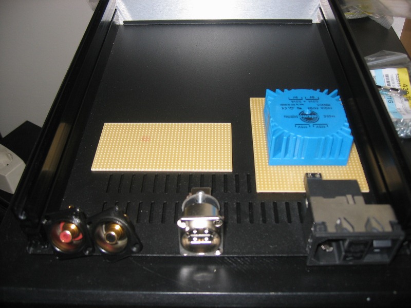
The first parts arrived today, took quite a long time. Usually its faster. hm.
Well here are some Pics:


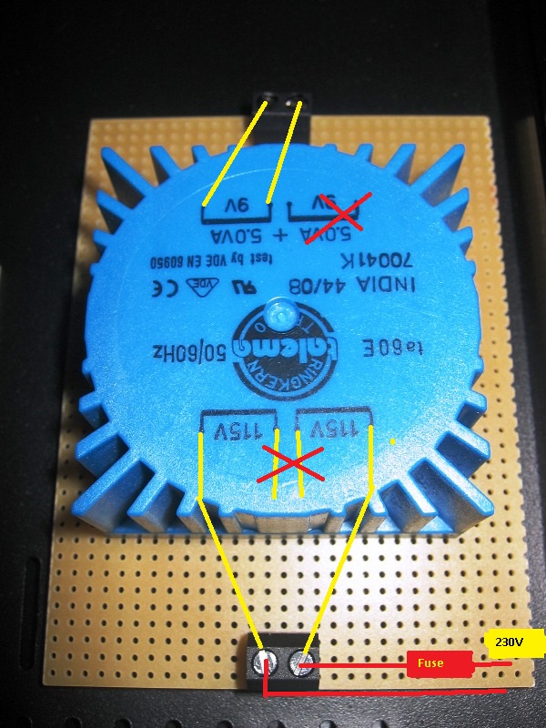
In the first picture i used paint to show the connections, are they right ?
Im not sure with the 230V connetion, maybe you have to connect the end and the beginning from the 115 parts, where i made the red cross. 😕
Well here are some Pics:


In the first picture i used paint to show the connections, are they right ?
Im not sure with the 230V connetion, maybe you have to connect the end and the beginning from the 115 parts, where i made the red cross. 😕
The DAC sound best using
1 Output transformers?
2 Tube stage?
3 OP Amps?
The DAC with op amps as I know has a 2.5Vrms output levels at 1 kHz can anyone tell me the other two output stages how big is the output level? Which tube stage is best for this DAC?
I try only the anode follower from lampizator using a 6N6P tube. But in my opinion this DAC with LM4562NA sounds great, no hum, no hiss only the beautiful clean and warm sound.
Its all abot what sonds best to YOUR ears 🙂 btw. for me LM4562 sounds clean precise but sterile.
I realised the page doesnt show my uploaded images in their original size.
maybe it works now:
maybe it works now:
In the first picture i used paint to show the connections, are they right ?
Im not sure with the 230V connetion, maybe you have to connect the end and the beginning from the 115 parts, where i made the red cross. 😕
Yes you will have to connect the end of one 115v to the beginning of the other 115v winding.
You can use just one 9v out or if you need more power connect them in parallel..
Attachments

thx! in the middle of the next weak im going to get my backplate. until then the dac should have arrived too. thats very nice.. 🙂
Gigawork DAC
Hello, this is my first post here so be gentle 🙂
I ordered a DAC from Hong Kong (Gigawork 24/192 Up-sampling DAC DA CONVERTER w/ USB kit)..
But it did not came with any drawings or anything.. so I just wonder if anyone have tried this unit before?
In case someone have tried it, how do I adjust this after it has been assembled? It came with an extra print board (a small one).. but I\m not shore what it is for.. and it came with a lot of jumpers..
I want to use this DAC to improve the sound from my HTPC.. But DAC is a new "world" to me 🙂
So any help will be appreciated..
Sorry for my poor English.. (I`m from Norway he he.. )
There should a small CD that contains some info about the settings.
The little board the the upsampling board. The CD has a picture to show how to use it. Some kind soul attached these in previous posts. You can get the same info if you don't have that CD.
BTW, the new version is labeled to accept PCM1793, 94, and 98 in additional to the CS dac. I wonder anyone knows a place that I can just buy the PCM dac board to try out ....
Hi,
I'm planning on purchasing either the CS4397 or CS4398 boards and performing the mods listed throughout this thread (replace filter components and bypass output with transistor).
Given I'm a complete DIY noob, I've just got two questions before I purchase (I'll definitely have more questions later!)
1. Should I get the standard power transformer that come with the kit or upgrade? Would the EI 15VA 2x15V from Harbuch (E I) be suitable?
2. Which board is easier for the beginner to work on - the CS4397 SMD or CS4398??
Thanks in advance and thanks to all the posters give up their time to help us beginners out!
Michael.
Hi Michael,
I still suggest the upsampling version of the CS4398 board. The 8421 up sampling chip is much improved over previous generations, very smooth and articulate.
If you are going to try the opamp output circuit you will need a power trafo similar to the one offered by the seller with 12-0-12 and 8-9v windings. If you do away with the opamp circuit all you need is a single 7-12VAC trafo. The load is less than 250ma on the digital side so you don't need anything big.
Best, Bill
The solder used by the manufacturer seems to be a problem for most. I reflowed the joints to be separated, adding some lead/tin solder, seemed to help separating the joints. I use a solder sucker from RadioShack, works great. Be gentle on the circuit traces, they are pretty fragile.
Data, I'm looking at Cinemag transformers for my dac. I'm a total newb but I'm curious; why did you choose the CMOQ-2 over the CMOB-2?...I also did a lot of research into it while looking at transformers.
Received my board today, it is printed V9 now.
Which DAC? Or are those big ones all the same? Do anyone have pics/schema from V9? What is changed?
pics/schema of v9
I have pics and schematics for versjon 9, if you would like 🙂 send me mail or post..
I have pics and schematics for versjon 9, if you would like 🙂 send me mail or post..
The schematic came with the CD is still N-versions behind 😉 The dac is labeled CS4397, and mine is the big dac!! It looks very much like V5 posted previously except 2 caps and 2 resistors after the first dac are now jumpers. For the mod to bypass the 2nd opamp, this is handy.Which DAC? Or are those big ones all the same? Do anyone have pics/schema from V9? What is changed?
- Home
- Source & Line
- Digital Line Level
- Experience with this DIY DAC ?