Lightspeed remote control
Hi Troy,
My camera is dead. I will have to get a new one. I am too busy with work at present, to assess which camera would suit my present needs, so it will have to be after new year.
If you follow the layout drawings I posted you should be able to assemble the modules without problem.
Regards
Paul
Hi Troy,
My camera is dead. I will have to get a new one. I am too busy with work at present, to assess which camera would suit my present needs, so it will have to be after new year.
If you follow the layout drawings I posted you should be able to assemble the modules without problem.
Regards
Paul
Okay,
I kind of doubted that noise from LEDs could get through to the resistor side.
Today I was using an OLD 10 turn wirewound pot to control LDRs. It was a little scratchy as old wirewounds can be. There was one spot in the rotation I could go back and forth over and get the same result. What result? Well, you could hear the noise from the sparking in the pot but you could hear it in the speakers. So found that interesting and thought you guys might want to know.
I guess I will try snubbing the LED side and let it be. It doesnt bother me but makes me more aware that power supply matters.
Uriah
Just FYI
I suppose you all know that Philips had already a lightspeed included in the electronic organ "Philicorda" in the sixties. It was a 6,3 volt (bike)bulb built into a pedal. The bulb threw more or less light on a LDR inside the pedal by mechanical way (vary the shielding). Sorry my English is limited but I hope you get the idea.
I suppose you all know that Philips had already a lightspeed included in the electronic organ "Philicorda" in the sixties. It was a 6,3 volt (bike)bulb built into a pedal. The bulb threw more or less light on a LDR inside the pedal by mechanical way (vary the shielding). Sorry my English is limited but I hope you get the idea.
Hi
A while ago I built a Lightspeed clone on strip-board, it performs really well apart from a power supply issue.
Two of my walwarts got very warm and started to smoke. I put the first one down to a duff power pack, but now that a second has failed in the same way there is obviously an error in my circuit.
I've checked the regulated +5v supply wiring and it seems fine. The 7805TS regulator remains cool.
:: DatasheetPro :: Download TS7805 datasheet PDF download :: Taiwan Semiconductor Company Ltd. :: TS7800 series 3-Terminal Fixed Positive Voltage Regulator
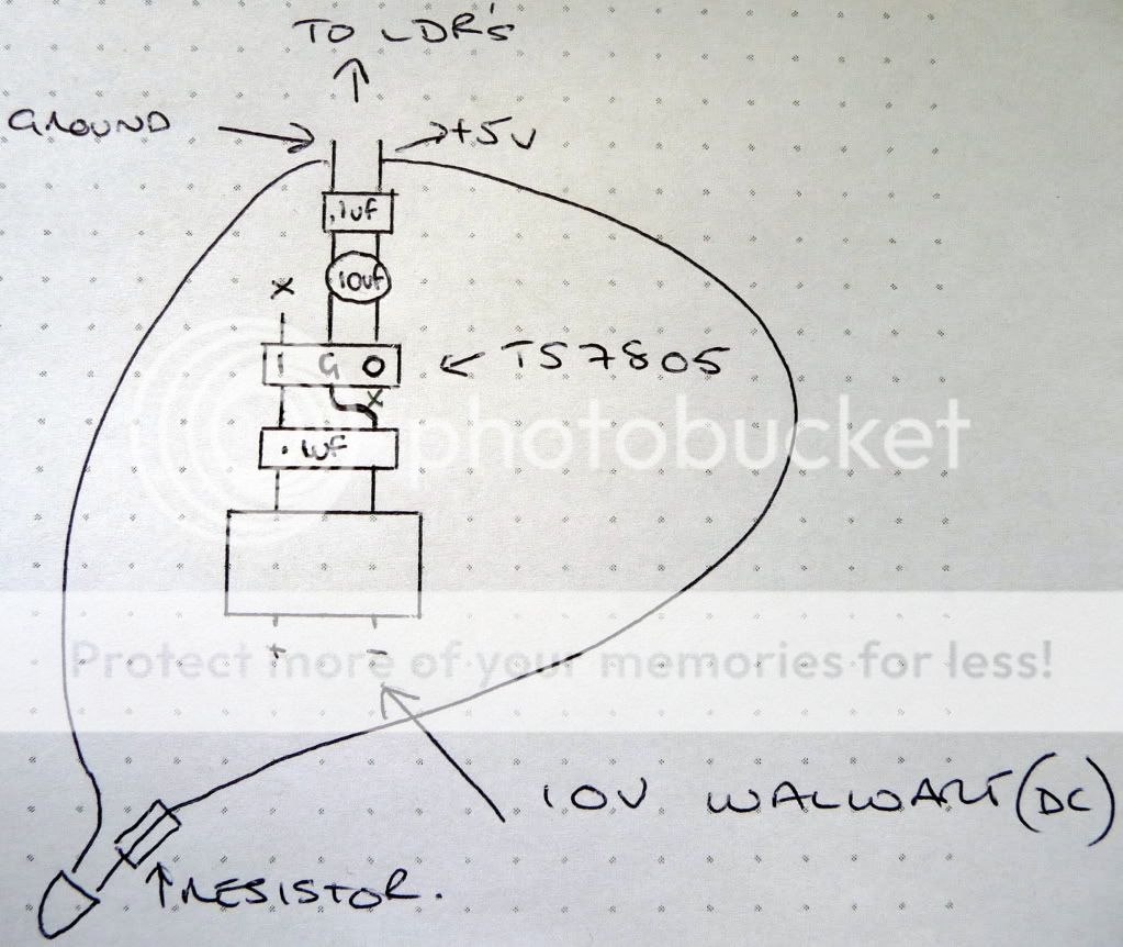
Any ideas? I'm a bit foxed as it appears to work OK...for a while that is.
Thanks 🙂
A while ago I built a Lightspeed clone on strip-board, it performs really well apart from a power supply issue.
Two of my walwarts got very warm and started to smoke. I put the first one down to a duff power pack, but now that a second has failed in the same way there is obviously an error in my circuit.
I've checked the regulated +5v supply wiring and it seems fine. The 7805TS regulator remains cool.
:: DatasheetPro :: Download TS7805 datasheet PDF download :: Taiwan Semiconductor Company Ltd. :: TS7800 series 3-Terminal Fixed Positive Voltage Regulator
Any ideas? I'm a bit foxed as it appears to work OK...for a while that is.
Thanks 🙂
There is nothing wrong with that circuit you posted. I could only say that maybe the 10uF goes before the regulator but still it makes no difference as far as smoking power packs.
I havent a clue. Maybe you should put a fuse on the AC side of things and see if it blows. Then if it does, put another on the DC side of things and see if it blows. This would tell you if its the power pack or the circuit. If both blow its the circuit if just the AC side blows its the power pack. I suppose you could just measure current in both those places and find the same thing.
----it would take tiny fuses to figure this out, so I think measuring current is a better thing to do.
Uriah
Hi,
what is the rated voltage of the wallwort?
What is the measured voltage?
What is the measured voltage at the regulator when the circuit is connected?
what is the rated voltage of the wallwort?
What is the measured voltage?
What is the measured voltage at the regulator when the circuit is connected?
Hi Uriah
I'm using an ac-dc walwart, I cant imagine its the power pack as I have tried two different makes and rated outputs. I know of another person who independently built a light speed and he has also blown two adaptors. But hasn't had any problems of late.
Its really strange 😕
I'm using an ac-dc walwart, I cant imagine its the power pack as I have tried two different makes and rated outputs. I know of another person who independently built a light speed and he has also blown two adaptors. But hasn't had any problems of late.
Its really strange 😕
Hi
A while ago I built a Lightspeed clone on strip-board, it performs really well apart from a power supply issue.
Two of my walwarts got very warm and started to smoke. I put the first one down to a duff power pack, but now that a second has failed in the same way there is obviously an error in my circuit.
I've checked the regulated +5v supply wiring and it seems fine. The 7805TS regulator remains cool.
:: DatasheetPro :: Download TS7805 datasheet PDF download :: Taiwan Semiconductor Company Ltd. :: TS7800 series 3-Terminal Fixed Positive Voltage Regulator
Any ideas? I'm a bit foxed as it appears to work OK...for a while that is.
Thanks 🙂
Tried batteries? If they go up in smoke then there is something seriously wrong!😀
Good idea Alan!
I have tried a wallwart with no trouble and my circuit was about the same as yours but with LM7805. Pretty much same thing.
Uriah
I have tried a wallwart with no trouble and my circuit was about the same as yours but with LM7805. Pretty much same thing.
Uriah
Tried batteries? If they go up in smoke then there is something seriously wrong!😀
Hi Alan
Yes I have. I ran it from a 9v battery and it worked fine for about an hour and then the LED glowed dimly and the speaker output decreased.
Could this be a clue?
Hi,
what is the rated voltage of the wallwort?
What is the measured voltage?
What is the measured voltage at the regulator when the circuit is connected?
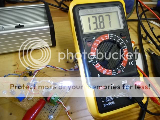
I will check again...I remember using a 6v rated pack that outputted around 9-10v from memory. The voltage after the regulator was 5v
You have to look where the short is. Perhaps in the wrapped up led ?
Hi
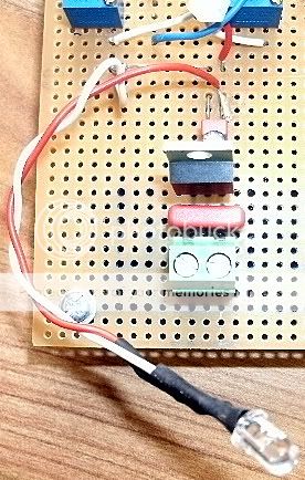
The LED legs are separate (heat shrinked from one another) so there shouldn't be a short there.
Hi
What would happen if the Display LED,series resistor had too much resistance? Apart from dim illumination, could it effect anything else?
Thanks
What would happen if the Display LED,series resistor had too much resistance? Apart from dim illumination, could it effect anything else?
Thanks
The LED and it's current limiting resistor is just an indicator telling you the unit is powered up.
It does nothing for the audio.
The loss of volume at the speakers as the battery went down tells us that the LDR is reacting to the reduced current supply. As the LED current drops the LDR resistances rise and eventually you have a -6dB fixed resistance attenuator.
The voltage at the input to the regulator is required, not the output of the regulator.
The LED and it's current limiting resistor is just an indicator telling you the unit is powered up.
It does nothing for the audio.
The loss of volume at the speakers as the battery went down tells us that the LDR is reacting to the reduced current supply. As the LED current drops the LDR resistances rise and eventually you have a -6dB fixed resistance attenuator.
The voltage at the input to the regulator is required, not the output of the regulator.
Hi Andrew
I know the LED is only an indicator, but I wondered if the excessive resistance in the series resistor was causing a problem in the power pack. I'm guessing not
I am currently using a 12v DC 1A adapter. The voltage at the regulator input pin is 14.45v
I have disconnected the LED
I have disconnected the LED
- Home
- Source & Line
- Analog Line Level
- Lightspeed Attenuator a new passive preamp