Hi!
I am trying to modify the power supply of my CD transport Audiomeca Mephisto 1 but I have no schematics. It is Philips CDM 9/44 based CD transport. It has Philips CD850 like power supply. I am trying to understand the schematic. Can somebody explain me the function of C854, D854 and D855 of Maranzt CD63/67?
I am trying to modify the power supply of my CD transport Audiomeca Mephisto 1 but I have no schematics. It is Philips CDM 9/44 based CD transport. It has Philips CD850 like power supply. I am trying to understand the schematic. Can somebody explain me the function of C854, D854 and D855 of Maranzt CD63/67?
Attachments
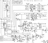
These parts act as a voltage doubler. You may have noticed the input voltage is 13.6VAC, and from that the -31.8V for the display is created.
Regards,
Ray
Regards,
Ray
OK I went back to Brent's mod list and found that I need a muting circuit on each channel. Can somebody tell me where to get the 10v and signal inputs from?
First of all - Congratulations Ray!
I have try to simulate the Marantz's voltage doubler here but it did not work. It is not so important...
I few days ago I started to read this tread with hope to learn something and to find some answers. But it has “a few pages” more than the other treads so I will have to use some short cut questions if you do not mind.
What is your final solution for servo board power supply? I have heard that the regulators like 317/ 337 or regulators with feed-back are not a good solution because the drivers for transport's motors are working in pulse mode so it makes “noises”. The better way should be a power supply based on zener follower + (choke?) + cap multiplier + some capacitors.
What is your opinion?
Regards,
Alex
These parts act as a voltage doubler. You may have noticed the input voltage is 13.6VAC, and from that the -31.8V for the display is created.
Regards,
Ray
I have try to simulate the Marantz's voltage doubler here but it did not work. It is not so important...
I few days ago I started to read this tread with hope to learn something and to find some answers. But it has “a few pages” more than the other treads so I will have to use some short cut questions if you do not mind.
What is your final solution for servo board power supply? I have heard that the regulators like 317/ 337 or regulators with feed-back are not a good solution because the drivers for transport's motors are working in pulse mode so it makes “noises”. The better way should be a power supply based on zener follower + (choke?) + cap multiplier + some capacitors.
What is your opinion?
Regards,
Alex
After about 10 hours of break-in, the sound of my new Oscon SA's changed from grainy to muffled. It sounds a bit like one of the veils that has been lifted by previous mods is put back. Also bass isn't as deep as it used to be. Soundstage is good though.
Current setup:
cd04/07 - Raygulators with noname 100uf caps on the output
cd05/06 - Oscon SA 100uf
cd15/16 - Elna Silmic salvaged from output stage of cd63SE
Strange. Not sure I want to keep it this way...
Current setup:
cd04/07 - Raygulators with noname 100uf caps on the output
cd05/06 - Oscon SA 100uf
cd15/16 - Elna Silmic salvaged from output stage of cd63SE
Strange. Not sure I want to keep it this way...
The noname caps and the OsCons are in parallel so it seems. You need only one electrolytic at the regulator's output (or at the IC's power pin), so I'd remove one of them. Try the noname first. If that doesn't improve things, the OsCons could be the cause. They have very low ESR, and it could be the LM regulators are unstable because of that.
Regards,
Ray
Regards,
Ray
First of all - Congratulations Ray!
Thanks Alex 😀
I have try to simulate the Marantz's voltage doubler here but it did not work. It is not so important...
I few days ago I started to read this tread with hope to learn something and to find some answers. But it has “a few pages” more than the other treads so I will have to use some short cut questions if you do not mind.
What is your final solution for servo board power supply? I have heard that the regulators like 317/ 337 or regulators with feed-back are not a good solution because the drivers for transport's motors are working in pulse mode so it makes “noises”. The better way should be a power supply based on zener follower + (choke?) + cap multiplier + some capacitors.
What is your opinion?
Regards,
Alex
That voltage doubler works by the same principle, it's only a different setup. Two capacitors are charged, each one on one half of the sinewave cycle. By connecting them in series, double output voltage is obtained. The doubler in the player used one cap in series with the AC winding (C854) that is charged during one half of the cycle, and during the other half it appears in series with the AC winding and the voltage is lifted by the DC value present at that cap. The second cap C852 doesn't really take part in the doubling process, but is only charged with the resulting voltage, and diode D851 prevents it from flowing back into the doubler.
Last edited:
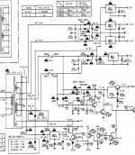
As for the servo supply, in a CD63 the servo voltages are unregulated, so serious gains can be made here. In a CD67, the supply is regulated with a 7805. Most of the standard regulators have fairly good load regulation (only 2...15mV voltage change for full load ON/OFF) and should be able to deal with the PWM driven motor current. The step response is improved drastically by adding a few uF of output capacity, so the 100uF or more in the player should provide plenty buffering.
I can imagine that in some cases the regulator can become unstable with large output caps, I have seen this several times now with the new ONSemi regulators (MC78xxCT series), the ones with the thin metal tab on the housing. An output cap over 100/220uF will make these things oscillate for sure. I have stopped using them and use the ones from ST or NSC now. In the race for smaller and smaller output caps they probably changed the circuit.
I never tried a passive supply based on a choke here, but it has the advantage that it is a very effective barrier for noise, and won't go berserk with large output caps. You should make sure that the output impedance is low enough when using a passive circuit (something that can be easily realized by feedback) or the cure may be worse than the problem.
Regards,
Ray
The noname caps and the OsCons are in parallel so it seems. You need only one electrolytic at the regulator's output (or at the IC's power pin), so I'd remove one of them.
Yep! That worked. Could somebody tell me the 'theoretical' background why the parallel caps sounded as they did (muffled). I have similar setup around the servo (lm317 with 100uf noname cap), and looking at the the schematics, this cap is in parallel with c119/120 and c121/122... Without the theoretical background it's hard to understand whether to remove this one as well.
c119/121= small axial ceramic 0.047
c120/122= 47uf
cap on reg = 100uf, feeding both analog and digital supply to servo
Last edited:
Here's my pseudo-science answer:
Theoretically more caps in parallel could be better, but too low impedance at certain frequencies could cause the circuit to resonate/ring or upset other things like voltage regulators and hence it sounds bad. It seems a smooth and low impedance curve is what we want.
A rule of thumb for capacitor bypassing I heard is to use 1/10 of the capacitance, e.g. 1000uF cap should be bypassed with a similar cap of 100uF. 100uF would be bypassed with 10uF. It is rarely done like this in practice, for some reason - perhaps because for analogue circuits it's usually not done at all, and in digital ones the small film caps are there specifically to deal with really high frequency noise.
Much smaller bypass caps can cause a sharp resonance and that is perhaps audible in how it effects the circuit. The resonance can be damped by a resistor, and then you have a snubber circuit. Something like 100nF and 1R has been used in power amplifier power supplies.
As for mixing electrolytic caps I don't know why it's technically bad but there have been various accounts by the keen-eared of these combos being hit and miss sonically. The sound being "confused" has been mentioned before in other threads!!
Simon
Last edited:
I had similar issues when paralelling different types of EL.
Even as psu smoothers, different build EL can produce an incoherent sound.
Ricardo
Even as psu smoothers, different build EL can produce an incoherent sound.
Ricardo
Ray - congrats..
Thanks avr! She's a really sweet little girl, only not last night!
 😀
😀Ray
Interesting...
I might take them off everywhere were they are in parallel:
+/- 12V rails (since the lm317/337+caps are in parallel with c805/806)
Servo (since in parallel with 2 other caps on each supply as well)
However... on Ray's pictures I see that he retains the caps on the regulators for the +/-12V rails. No electrolytes though
This effect doesn't seem to apply or is less pronounced if there is some physical distance between the caps e.g. cap after regulator is different to local decoupling cap.
Simon
Simon
Just done a couple more tweaks on Steve's CD63, partly for my own amusement.
I changed C505 to a 2200pF polystyrene (HF signal runs through this), as well as C601-C602 filter caps to ps. I also put a slightly better cap on C814 (-10V).
The sound is certainly more open and coherent. Very nice improvement for a few cheap part swaps.
Simon
I changed C505 to a 2200pF polystyrene (HF signal runs through this), as well as C601-C602 filter caps to ps. I also put a slightly better cap on C814 (-10V).
The sound is certainly more open and coherent. Very nice improvement for a few cheap part swaps.
Simon
There's some genuine big earthy detail coming off the piano on Diana Krall now, Steve's gonna be a happy man...!
Any issues with the sound on this player are v slight now and would almost certainly disappear with a couple of low noise regs and better output stage, plus the servo re-clock... it never ends really.
Any issues with the sound on this player are v slight now and would almost certainly disappear with a couple of low noise regs and better output stage, plus the servo re-clock... it never ends really.
Hi Simon
I believe you are now hearing the effect of the C505 2200pF polystyrene.
It is one of the most revealing mods I did.
Ricardo
I believe you are now hearing the effect of the C505 2200pF polystyrene.
It is one of the most revealing mods I did.
Ricardo
Hi Ricardo,
I'm glad you commented on this. I strongly suspected the improvements were 90% that cap. To look at it in the service manual it looks very important, and to see in the flesh this puny cheap ceramic toilet-waste cap I felt it would be a good price-performance ratio mod!
Simon
I'm glad you commented on this. I strongly suspected the improvements were 90% that cap. To look at it in the service manual it looks very important, and to see in the flesh this puny cheap ceramic toilet-waste cap I felt it would be a good price-performance ratio mod!
Simon
- Home
- Source & Line
- Digital Source
- Marantz CD63 & CD67 mods list