new sound card, new measurements
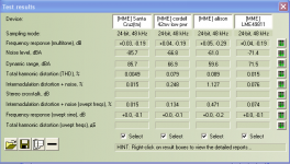
New sound card arrived today Gina 3
Card THD measures 0.0019.
Remeasured the EF scheme, the Allison A/B and the LME49811 alone. All at low power until I make my attenuation setup. What you'll see is that the Allison A/B doesn't add any additional distortion over the LME49811. Tried it twice with the same results.
Paul, I also ran the Allison A/B into 8 ohms at 36 volts peak to peak - it clips at 49vpp on +-30.5v measured at the main supply caps under load. I measured the emmitter to emmitter voltage at 1.169v at start up. After the hard run, I measured 1.130v. The diodes were slightly warm to touch as were the driver transistors, say 90deg F. As they cooled down the voltage slowly rose to 1.165v.
Ken L
p.s. darn, posted the wrong results, these are the old ones...
Attachments
Last edited:
The next few posts will be the graphics. The one labeled Cordell is a single driver, single output Thermal Trak transistor with the bais scheme by Bob Cordell from the Thermal Trak thread. The driver and output transistors are the same types for both schemes mjl15032/33 drivers and njl3281/1302 output.
Ken L
Ken L
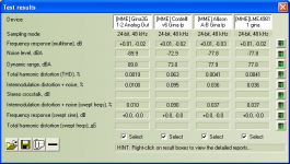


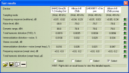
The correct results.
Are these results from 8 ohm loaded conditions?
MJL,
Yes, it was tested with the compensation removed. I thought it was running well without, but apparently not.
Ken L
Are these results from 8 ohm loaded conditions?
Hi Panson,
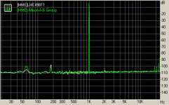
I'm a bit embarrassed 😱 ok, maybe a lot embarrassed. The results did look to good. I went out to the garage this morning and ran it again. I must have not connected the load last night, doing to many things at the same time. Darn, I guess I wanted to believe.... The results with the 8 ohm load for the Allison A/B with all the other settings the same are 0.019 THD. The LME was tested into a 1k load at both the sink and source.
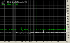
The Allison A/B graph was still quite flat and quiet with small spikes at 2k, 4k and 5k.
Ken
Hi Panson,
.... The LME was tested into a 1k load at both the sink and source. ....
Ken
Hi Ken,
Ha ha .. I made similar mistakes several times.
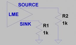
The LME was configured like this figure?
Panson
Attachments
Hi Ken,
Ha ha .. I made similar mistakes several times.
The LME was configured like this figure?
Panson
Hi Panson,
So, your's was a knowing question. Regarding your diagram, yes but, the Rf is tied in there as well.
Ken L
new test results
After spending most of the day yesterday struggling with the amps, I have figured out that my grounding was all goofy. Why it raised it's ugly head yesterday and not before, is a big mistery to me. Basically, I have all the signal grounding going through a 10 ohm resistor to the power ground and have also put a ground wire between the computer and the power ground. This last move took out a 12db hump in the 60 hz region.
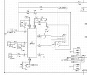
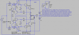
I've built a new driver board with the caps shown on Paul's latest schematic I made them with jumpers so that I could try it in several ways. I've attached the schematic.
I made a few other tweaks to the board and the THD came down .01.
Attached the results and the schematic. In the results, the Allison A-B -25db test (second from left) jpr3 is in place and jpr1 and 2 are open. In Allison A-B -25 pcomp, jpr3 is open and jpr1 and 2 are in place. I realized that I should try one more combination and that is Jpr3 and 1 open and jpr2 in place. Pin 4 of the header goes to the point x on Paul's schematic.
After spending most of the day yesterday struggling with the amps, I have figured out that my grounding was all goofy. Why it raised it's ugly head yesterday and not before, is a big mistery to me. Basically, I have all the signal grounding going through a 10 ohm resistor to the power ground and have also put a ground wire between the computer and the power ground. This last move took out a 12db hump in the 60 hz region.
I've built a new driver board with the caps shown on Paul's latest schematic I made them with jumpers so that I could try it in several ways. I've attached the schematic.
I made a few other tweaks to the board and the THD came down .01.
Attached the results and the schematic. In the results, the Allison A-B -25db test (second from left) jpr3 is in place and jpr1 and 2 are open. In Allison A-B -25 pcomp, jpr3 is open and jpr1 and 2 are in place. I realized that I should try one more combination and that is Jpr3 and 1 open and jpr2 in place. Pin 4 of the header goes to the point x on Paul's schematic.
Attachments

Last edited:
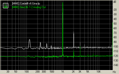
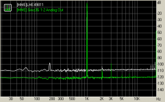
graphs
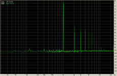
The following are the THD graphs from the results. The second graph shows the sound card along with the Allison A-B. Still waiting on the post office to receive resistors to build the attenuator and see how things look at high power.
Ken L
I thought the graphs would have header labels... the first is the Allison A-B as shown in the second spot from the left in the results file, the center graph is what I mentioned above and the left graph is the Allison A-B -25db pcomp as shown on the far right on the results file.
Attachments

Last edited:
After spending most of the day yesterday struggling with the amps, I have figured out that my grounding was all goofy. Why it raised it's ugly head yesterday and not before, is a big mistery to me. Basically, I have all the signal grounding going through a 10 ohm resistor to the power ground and have also put a ground wire between the computer and the power ground. This last move took out a 12db hump in the 60 hz region.
I've built a new driver board with the caps shown on Paul's latest schematic I made them with jumpers so that I could try it in several ways. I've attached the schematic.
I made a few other tweaks to the board and the THD came down .01.
Attached the results and the schematic. In the results, the Allison A-B -25db test (second from left) jpr3 is in place and jpr1 and 2 are open. In Allison A-B -25 pcomp, jpr3 is open and jpr1 and 2 are in place. I realized that I should try one more combination and that is Jpr3 and 1 open and jpr2 in place. Pin 4 of the header goes to the point x on Paul's schematic.
somehow I keep posting the wrong results file... hopefully, here's the correct one.
Attachments
And here is my latest work on the variable AB Allison.
If it's going to be knob-variable, it should have some protection against disconnects. Unfortunately, the protection scheme will make the bias control a little nonlinear. This won't affect distortion.
This is necessary, since if the POT disconnects an indefinite amount of bias current will flow until something explodes.
NOTE: Rmax starts at a low value before adjustment, but Rmin starts at a large value, say above 68 ohms.
- keantoken
Attachments

When I ran the tests shown above, Rin1 was still 1k and Cc1 was 220pf polystyrene cap. I changed Rin1 to 100 ohms and things got worse. I changed Rin1 back to 1k, but, no luck returning to the previous results. I removed Cc1 and it returned finally returned to the previous good results. I had started to think that I had not connected the load for the previous tests, but, I was able to verify that the previous results were not a fluke.
I also tried different changing Cc1 to 15pf, no go. Also Cc2 at 33pf, no go, also 100pf, again worse than the original.
The either the Allison or the LME49811 don't like to have the compensation from the LME49811 tied to point x (the connector between the emitters of the Allison pair).
Attached is the schematic that seems to be working well, at least in the past few minutes 😉 .
Ken L
Attachments

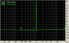
Ah, that's better! Into what load is this?
Thanks,
- keantoken
Yes, only .001% THD added to the LME49811. So, now I'm working on trying to get better performance out of the LME49811...
Ken L
And here is my latest work on the variable AB Allison.
If it's going to be knob-variable, it should have some protection against disconnects. Unfortunately, the protection scheme will make the bias control a little nonlinear. This won't affect distortion.
This is necessary, since if the POT disconnects an indefinite amount of bias current will flow until something explodes.
NOTE: Rmax starts at a low value before adjustment, but Rmin starts at a large value, say above 68 ohms.
- keantoken
Keantoken,
Can you post the THD numbers at say 2v input and 30v input.
I do think in real application, it will need compensation. Though I've reduce the 100 pf to 33pf without a change in the results. I'm wondering if I can or should reduce the 560 ohm resistor as well. Any thoughts?
Ken L
Which class should I simulate in? I just simulated in class A and THD numbers were .000001% and .000074%... I expect real numbers to be 10 to 100 times this when the LME's own distortion is factored in. In class AB with 100mA bias, THD is .000129% and .000131%.
If the 33p is as low as you can go, then there should be nothing wrong with lowering the resistor as well. Lowering the compensation will reduce THD.
- keantoken
If the 33p is as low as you can go, then there should be nothing wrong with lowering the resistor as well. Lowering the compensation will reduce THD.
- keantoken
Attachments
Last edited:
- Home
- Amplifiers
- Solid State
- Simulation Analysis of several unique Allison-based output stages.