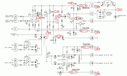
Thanks for the scheme, the end only one question, do the amplifiers can be the power supply Us = ± 60V, and that changes should be done?
Thank you!🙂
Thank you!🙂
@Wasim
Nice to hear everything is OK (as it should be!). Listen for a few days and then tell us your impressions.
@radio
Yes, it is safe to run it on +/-60V DC but NOT MORE than that! Everything else can be as is. Under such condition, amp is suitable for 8 ohms loads but not for 4 ohms!!! For work with 4 ohms loads you will need to add two more transistors in each rail accompanied with emitter resistors! You will also have to change R24 into 0,075 ohms/5W one.
@Wasim
Nice to hear everything is OK (as it should be!). Listen for a few days and then tell us your impressions.
Thank you for your response!
Since disposal Impedance 4oma with speakers, amplifiers'll do this with 6 output transistors. Prayed would, if you are able to send this PCB amplifiers!
Thank you in advance!🙂
Sorry English speaking members, ONLY THIS TIME I have to write just a few sentences to RADIO in my native Serbian... or it might take few pages this way...
Za rad na 4 oma treba dodati jos po dva izlazna u svaku granu napajanja! Ne moze sa 6 komada! Nemam plocicu jer sam to konstruisao jos krajem '70-tih a tada nije bilo PC-a. Nacrt je bio na papiru ali ja vise ne mogu da ga nadjem. Moraces sam da konstruises plocicu ili zamolis nekoga. Ne moze bas sve na gotovo!
Za rad na 4 oma treba dodati jos po dva izlazna u svaku granu napajanja! Ne moze sa 6 komada! Nemam plocicu jer sam to konstruisao jos krajem '70-tih a tada nije bilo PC-a. Nacrt je bio na papiru ali ja vise ne mogu da ga nadjem. Moraces sam da konstruises plocicu ili zamolis nekoga. Ne moze bas sve na gotovo!
Sorry but you can not. You need complementary pair with about 250V / 4A / 20-50W and in TO220 package.
Hi Dear Sir,
The Techno sounds really great. I have few friends invited at home. They are music lovers and I am going to play Legend stage master and Techno I will write their comments soon about your designs. And I am sure they would love it.
Sir, one small thing I would like to ask now I am very much interested making 3 way active crossover do you have any design for that ?
Regards
3way Active crossover
Sir This is very fine. Can I have its PCB and all files?
Regards
Sir This is very fine. Can I have its PCB and all files?
Regards
Xover
Thank you Sir I got the files
Regards
Check your E-mail Wasim!😎
Thank you Sir I got the files
Regards
Hi Sir, I want to know the 100 ohm trim pots are for the frequency set for the bass mid and tweeter? How can we adjust those? Sorry Sir this is my first Xover project 🙂
Regards
Wasim
Regards
Wasim
Omni Protection
Dear Dr. Bora
I produce yr. OMNI protection circuit but unfortunately couldn't able to work it yet.😕 led is always lightening and relays never switched on. I was already red following voltages and used resistors as per attached diagram. Relay brand is "SONGLE" ,"SRD-12VDC-SL-C"
Could give me yr. most valuable advices as designer of this circuits?
Thank you very much in advance.
Best regards
Attachments
Something is very wrong in your unit Duran!!! How do you explain that you have measured +36,5V across ZD2 (that voltage is OK) but then only +1,2V on the upper wire of the 68k resistor? That is the very same wire!!! Also, you have +13,3V across ZD3 when you should measure -13V there (voltage there should be negative with respect to ground!).
For your info, that unit has been done successfully at least several hundred times up to now… “Viktor1986” is one of them, he can tell you that.
For your info, that unit has been done successfully at least several hundred times up to now… “Viktor1986” is one of them, he can tell you that.
- Home
- Amplifiers
- Solid State
- Bora is a nice guy from Serbia - Yugoslávia

