I found your mistake JUMA.
You can't go directly to ground. You need to go through the Jfet source resistors to ground.
See the attachment for the corrections.
You can't go directly to ground. You need to go through the Jfet source resistors to ground.
See the attachment for the corrections.
Attachments
Last edited:
Be careful when biasing this one. It quickly goes from 2.4A to 3.7A with about 30 to 50 ohms adjustment on the trimpot.
Maybe the best solution would be a 300 Ohm resistor in series with a 500Ohm multi turn trim pot.
Or a parrallel solution could be better. Just need to determine the ball park first, before tweaking the bias control.
It might be less sensitive with less voltage at the base of the transistor.
From memory my bipolar cascode version was less sensitive with 4V at its base, I could be wrong though. I am going on gut feeling from how I remembered it when adjusting bias.
Anyway this one works.
Last edited:
Nice
Sure hope this is ok
You guys are great
Is there an easy way to connect a small panel ampmeter to monitor bias, without ruining anything ?
Sure hope this is ok
You guys are great
Is there an easy way to connect a small panel ampmeter to monitor bias, without ruining anything ?
Attachments
Last edited:
Thank for the test Thanh
I will modify the new lay out after your correction .
If you say that will work that good to know .
Thanks one more time
I have no access to do test on the circuit like you unfortunately .I have no scope also .
Greets
I will modify the new lay out after your correction .
If you say that will work that good to know .
Thanks one more time
I have no access to do test on the circuit like you unfortunately .I have no scope also .
Greets
As long as your layout matches the circuit it will work.
You need two multimeters. One measuring dc offset and the other measuring bias.
I would also use a lab power supply with adjustable current limiting when firing up for the first time.
To be safe. I would probably go with a 500Ohm multi turn trim pot first and if you need more adjustment then go bigger. You need reasonably good adjustment, with this circuit. Once you get to 2A it goes to 4A very quickly so make small adjustments.
Once you know the ball park we can implement a better bias control or if you are lucky enough you might be able to use fixed resistors.
Thanks for your contribution Juma.
Last edited:
Thanh
Thanks , I did set up many amplifier bias but still good to read your advise .I have more than 3 multimeter at hand that will be no problem .
If I use resistor and trimpot (both) to set up the bias what would be your recommendation . These way is more safe you wrote yesterday .
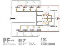
In case if you interested to see my layout I can send it to you if you provide your email address .
Of course I made the layout with my computer using only the paint program .
mathelaszlo2@yahoo.ca
Greets
Thanks , I did set up many amplifier bias but still good to read your advise .I have more than 3 multimeter at hand that will be no problem .
If I use resistor and trimpot (both) to set up the bias what would be your recommendation . These way is more safe you wrote yesterday .
In case if you interested to see my layout I can send it to you if you provide your email address .
Of course I made the layout with my computer using only the paint program .
mathelaszlo2@yahoo.ca
Greets
It would be nice if you can get hold of a lab power supply with current limiting.
It looks like you will be around 400 to 600 ohms, to be where you want.
This amp is a bit different from most in that each trim pot adjusts both bias and dc offset simultaneously. So take it very slowly.
Set your trimpots to 50 Ohms and slowly adjust upwards, a quarter of a turn or less on each trimpot.
Once you you are at 2.4A, watch it for an hour to be sure it is not still moving.
Then turn off your amp and measure the resistance of both trimpots, if you lucky you might be able to use fixed values.
Let us know how you go.
This circuit has been built many times in reality and it works perfectly. Sim software will tell you all kind off lies if you don't know how to use it properly.I made the poor assumption that Juma thoroughly checked his circuit.
I thought I better check it, before people started building it verbatim.
To put it simply, it does not work at all.
Do not build it.
Just to let you know i used bc560 and bc550.
Juma can you check that you haven't made a simple mistake somewhere.
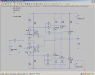
Tere are no mistakes in the circuit I have drawn. You should learn more before you start to believe blindly to your sim software.I found your mistake JUMA.
You can't go directly to ground. You need to go through the Jfet source resistors to ground.
See the attachment for the corrections.
Your sch. will work but with worse performance (JFET's Vds should not be constant in this case)
Hi Juma!
Yes, your circuit is as correct as it can be.
It's basic stuff, really 😉
you got PM 🙂
Last edited:
Hello Juma and Thanh
I made a lot of search on the net I find very popular well design amps similar way cascode how Juma drawn .These amp has a good reputation .
So I will go after His schematic to make my PC board .
Also I found circuit uses the same set up how Thanh made his firs test the difference they use JET for cascode not lateral
Probably both work .
Because I know these amplifier is a commercial (not cheap) amp and has similar cascode how Juma drawn I go with that .
The difference the designer use Zener diode wich goes to the ground .
Thank you guys for the help .
Greets
Hello
Yes you right , actually these is the Grand Mos schematic .I didn't wanted to post the whole schematic because that a commercial amp.
We just talking here about cascoding the right way .
Any comment , advise welcome .
Thank one more time Juma & Thanh , you guys are very helpful.
Greets
boyz - Papa said more than once that referencing cascode to gnd ( not source ) is part of linearizing jfet further ;
read sweet spot article ;
read sweet spot article ;
boyz - Papa said more than once that referencing cascode to gnd ( not source ) is part of linearizing jfet further
There is a trick worth knowing - You can use a potiometer
to reference to any point between Source pin and Ground,
tweaking for the sweet spot.
😎
There is a trick worth knowing - You can use a potiometer
to reference to any point between Source pin and Ground,
tweaking for the sweet spot.
😎
baaad Papa !
baaad !

- Home
- Amplifiers
- Pass Labs
- F5 power amplifier