Hi, circuitcity.
Spectraplus (http://www.telebyte.com/pioneer/)
Realtime analyzer (http://www.ymec.com/products/rale/)
Spectraplus (http://www.telebyte.com/pioneer/)
Realtime analyzer (http://www.ymec.com/products/rale/)
Hi Bender.ru
Thanks for your sharing.
I use irs20957 to do a new version ucd like amp,but hard to get a 400khz osc frequency.
Did you ever find this problem?
And also a very bad THD,the THD is 0.05 at 1w,but will be 0.25 at 10w,0.5 at 20w,1 at 30w.
I dont think this bad Thd is caused by my layout,my unit is a 4-layer pcb.
could you give me some enlighten?
Best regards
Hi, vincent s.
Oscillating frequency depends on shematic propagation delay time (tprop(comparator)+tprop(ic driver)...), LC, feedback network element nominals. My amp operates near 300kHz or little bit lower.
Pcb topology may be cause of such thd level. What about fet, dead time set by 20957?
Oscillating frequency depends on shematic propagation delay time (tprop(comparator)+tprop(ic driver)...), LC, feedback network element nominals. My amp operates near 300kHz or little bit lower.
Pcb topology may be cause of such thd level. What about fet, dead time set by 20957?
Hi Bender.ru
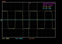
your osc frequency is about 300kz?but from the wave on you scope shows that it is 400khz.
My unit works at 290khz.
I also tried some diffrent DT,but cant get anything improved.
Because I use AP to test my unit,so there is difference between ours.
your osc frequency is about 300kz?but from the wave on you scope shows that it is 400khz.
My unit works at 290khz.
I also tried some diffrent DT,but cant get anything improved.
Because I use AP to test my unit,so there is difference between ours.
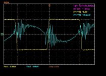
Early scope of early prototype design. v2,v3 osc frequency ~300kHz.
No matter how many layers pcb used, topology (+schematic) - key to success. Original 2 layer UcD modules has thd level ~0.05% (-3db) or better.
No matter how many layers pcb used, topology (+schematic) - key to success. Original 2 layer UcD modules has thd level ~0.05% (-3db) or better.
But 300khz osc frequency is too low,the 6.5khz will be very bad.
for topology,I tried many diffrent value componnents,but a problem still exist:the Thd will be much much more more worse than low power output.
I hope I could make it perform better than ucd module.
for topology,I tried many diffrent value componnents,but a problem still exist:the Thd will be much much more more worse than low power output.
I hope I could make it perform better than ucd module.
if you are using the AP do you have the AES17 filter fitted?
if not you will get much worse figures than using the PC sound card method; as this has an inherent brick wall filter at 21KHz
the basic 22KHz filter on the AP has a gentle roll off but still registers up to either the fs/2 using the digital DSP analyser or 500KHz if using the analogue meters
regards
Passive Poles
Dear Bender,
I think you made a good amplifier. Thanks for your sharing and congragulations! Your circuit works in the same principle like discrete UCD amps. But, your amp has less active components than discrete ones. Therefore it is more easy to implement. I saw several questions about the sw. frequency and it seems you answered them.
I would like to give some ideas for the diyers or you; the sw. freq. depending on the propagation delay and last faloating input IC from IR is IRS20957( 1st 20954), so to get lower prop. delay times one might use faster comparators like LT1016( some other variants from other companies for eg.; TI,Maxim etc.), LM 361 instead of LM311 and pherhaps playing with the FB RC components might increase the sw.freq. Also using complementary output comps. enable diyers to make full bridge amps using two driver and output mofets. There are also some questions about the THD level and now, I would like to ask a question; in orginal AES paper (from Buruno, thanks to him for his invention) the author describes using passive poles increases the thd performance. So have you ever tried adding passive poles into FB line of your desing to increase THD performance?(there is an example in philips FWM730 service man.). Also have you ever tried to implement a sync. osc. to your circuit? In my experiments I tried some 40-50kHz higher sync. osc. can result to UCD amp oscillating the sync. frequency( for eg.; free running freq. is 300k and when you sync it with 350k it runs at 350k).
I was following your theread but i miss the TO220 output layout and PCB of the circuit. So, please let me to know where is it? And please let us to know what do you think about the above ideas.
Thanks and regards
Smallest Hybrid amp
Dear Bender and all,
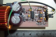
I realised that Bender and the others are not interested with the above questions. Anyway! Therefore I tried to make my own desing and get the smallest amp below. Bender, please excuse me if I get you bother by posting in your thread.
First of all simulate the shematic. I used the chip IRS20954S which is known as unsable( Make a diyaudio search) and old IC. I get it from Farnell, it is cheap for now. I did not faced a problem by implementing it. My output mosfets are IRFB5615PBF. SW frequency is 550-600kHz. Input comparator is MXL1016 from Maxim and sound is very good just for my firts testing. DT adj is max(45ns) for first test purpose. I think I have to decrase the sw frequency down to 400k and set the dead time into a suitible time(25ns?).
Regards
NB. If someone interested I can give the PCB toner file
Dear Bender and all,
I realised that Bender and the others are not interested with the above questions. Anyway! Therefore I tried to make my own desing and get the smallest amp below. Bender, please excuse me if I get you bother by posting in your thread.
First of all simulate the shematic. I used the chip IRS20954S which is known as unsable( Make a diyaudio search) and old IC. I get it from Farnell, it is cheap for now. I did not faced a problem by implementing it. My output mosfets are IRFB5615PBF. SW frequency is 550-600kHz. Input comparator is MXL1016 from Maxim and sound is very good just for my firts testing. DT adj is max(45ns) for first test purpose. I think I have to decrase the sw frequency down to 400k and set the dead time into a suitible time(25ns?).
Regards
NB. If someone interested I can give the PCB toner file
Attachments


how about if you make vid, showing amp playing, looking at waveforms, stuff like that, I would sure like that!
BTW, nice you on it, very impressive!
BTW, nice you on it, very impressive!
Ok. Luka, What song you want me to play?🙂. I have never do so kind of an upload but, I think I can do. The time is late now and I do not want to disturb my neighbours. So, tomorrow I will.
Regards
Regards
Any song, you chose, do it when ever you find the time, no need to rush 🙂
Maybe upload it to youtube for easy viewing for anybody that will want.
Maybe upload it to youtube for easy viewing for anybody that will want.
- Status
- Not open for further replies.
- Home
- Amplifiers
- Class D
- UcD like topology amp.