As described earlier, my jacks are all isolated from chassis.deepthrob said:A DIY wiring mistake I often see is using a shield to carry signal in a hi-z circuit. I find a shield is seldom needed but if it is, use a separate wire for the signal return (ground). Don't use the shield.
Another is using the chassis for signal ground. If you want a really quiet project, isolate all jacks from the chassis and run a ground wire to each one.
Frank
http://newmex.com/f10 [/B]
So the wiring from the jacks should consist of 3 wires; signal to signal, signal return to star ground and jack shield to star ground.
Should they be twisted?
Henrik
Yes, 3 wires, that's the trick if you need a shield. The shield only connects at one end. Since it doesn't carry signal, a convenient chasis gound is fine.
Without a shield, 2 wires for each jack.
Frank
http://newmex.com/f10
Without a shield, 2 wires for each jack.
Frank
http://newmex.com/f10
Nordskov said:Jarno, someone specificly wrote NOT to use the 2. primary to achieve B+. He was afraid of high voltage puncture of the windings. This is why I used two toroids back-to-back.
Do you think this is an issue?
I will look into your idea of a bass shift. In time I will experiment with different tonestacks. Maybe a four band parametric EQ from Rod Elliot.
Sorry for not seeing this earlier! I actually use a toroid which is specially made for tube preamplifiers, so I'm using a secondary for B+. Not a problem, still need to fit a proper fuse though, it works fine with 2amps fuse, but that's way too much, maybe 600-700milliamps fuses will survive turn-on currents.
Where did you find the special tube toroid? It must have set you back by a small fortune.
That's right, a 2 amp fuse is way too much. Even at 120V it's still 240W. In Denmark we use 230V, that equals 460W
That's a hell of a short circuit.
I use a 2 A right now, but I'm thinking about a 250mA slow burning fuse when I'm done.
That's right, a 2 amp fuse is way too much. Even at 120V it's still 240W. In Denmark we use 230V, that equals 460W
That's a hell of a short circuit.
I use a 2 A right now, but I'm thinking about a 250mA slow burning fuse when I'm done.
What is the purpose of the 1N914 diode in the original design? Is there a good reason it's there, or is this another case of someone forgetting than an LED is a light emitting diode and doesn't need another diode to rectify the supply? I'd just make the 68 ohm resistor a little bigger and lose the diode. Am I missing something here?
Thanks.
Reid
Thanks.
Reid
Well, these toroids aren't that expensive at Tube Town
But I bought it for even less in a complete package including nice caps, knobs, 19" enclosure and the toroid, on eBay.
Reid,
In the schematic on Free Info Society, the 1N914 is indeed there for the LED (the LED is also on the schematic). Since I have rectified a rectified heater supply, I didn't need this diode, and just used a resistor.
Jarno said:
Reid,
In the schematic on Free Info Society, the 1N914 is indeed there for the LED
My question was "why", given the low voltage, but I forgot about the hum balance pot. To answer my own question:
Because the 6.3V winding doesn't have a center tap tied to ground, depending on the setting of the pot, the reverse voltage on the LED could get as high as 6.3V, which is too high for most LEDs. That's not terribly high, and it might not be fatal given enough series resistance, but it would be a marginal design that was sensitive to the selection of LED.
Speaking of marginality, the design of the circuit also seems to imply that turning the hum balance too far in the other direction will make the LED go out - does anyone know if that actually happens on a real F2B? Yuck.
Reid

Hello, great thread so far!
I have a 35 year old F2-B I play bass through it, and nothing else sounds as good to me to this day.
I'm really good with a soldering iron, understand very basic electricity etc. but stop WAY short of saying I know electronics. Schematics give me the willies, but I think I can get through this one... If I have to. This would be my biggest electronics project though, so I kinda need some hand holding to get started.
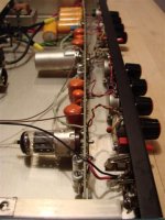
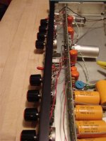
The last few years I've noticed the sound seems to have progressively dulled and lost it's life. The unit also has a little hum, and is pretty noisy. I was wondering if anyone could take a look at a picture and / or suggest the items I can replace which will restore it, maybe even make it sound better than new. All the resistors, etc. came with it originally, and it may have been re-capped back in the 80's but nothing has been done to it since then.
Here are the things I'd like to add or update with it:
It has an old 2 prong electrical cord with no safety ground - That can't be good when beer gets spilled on it.
I'm feeding the input with active EMG pickups. They have 200 ohms output impedance. Should I put a resistor on the input? I've read the F2-B really only likes passive pickups.
I'd REALLY like to make the main output a balanced 3 conductor connection instead of the unbalanced 1/4" one currently there, is that possible? All of the other gear in my rack is balanced in/out, and I use the rig in some really noisy environments!
I'm feeding a balanced TRS 10K ohms input (a compressor) from this unit. I don't really think I need more gain, I'd just like to ensure no hum from lighting, electrical, etc.. As well as giving the compressor the drive it wants to operate well.
=====================================
Here is some good advice I've been given so far elsewhere, can anyone add to or suggest changes? :
" ... Tubes and caps are the most likely for hum.
The orange ones are not electrolytics and do not need replacing. All cracked resistors obviously need replacing
Every one of the electrolytics needs replacing. The yellow ones and the silver ones.
If you want to quiet the noise, replace one of the resistors in the PS with a cheap choke -- it'll do wonders. - Replace the first 1K5 resistor with something like a hammond 154G
Replace the power cord! Particularly since you plug an instrument that you touch in to this, that should be fixed asap.
If you want a balanced output, use an output transformer -- Edcor would be good here, something like the XSM10K/10K would likely work well and could just be bolted to the output.
there is an issue which is that the Z out of the preamp is like 50K and won't likely do a good job driving the transformer's inductance. I think you should either work another tube in there (6T4 perhaps?) to lower the Z out so it can actually drive something like a cable, or the next stage, or you should switch from the 12ax7 to something with a lower rp -- maybe a 12ay7 or 12at7. The former will increase the signal a bit -- a 0.1u coupling cap will be too small in either case.
Assuming you do lower the impedance, on the primary you would connect out to + and - to ground (or the cathode if you like), and leave the input ct unconnected. For out, the "right" way to do it is to connect the + and - transformer taps to hot and cold, and connect the chassis (now grounded to safety ground) to the "ground" pin on the xlr.. ... "
I have a 35 year old F2-B I play bass through it, and nothing else sounds as good to me to this day.
I'm really good with a soldering iron, understand very basic electricity etc. but stop WAY short of saying I know electronics. Schematics give me the willies, but I think I can get through this one... If I have to. This would be my biggest electronics project though, so I kinda need some hand holding to get started.
The last few years I've noticed the sound seems to have progressively dulled and lost it's life. The unit also has a little hum, and is pretty noisy. I was wondering if anyone could take a look at a picture and / or suggest the items I can replace which will restore it, maybe even make it sound better than new. All the resistors, etc. came with it originally, and it may have been re-capped back in the 80's but nothing has been done to it since then.
Here are the things I'd like to add or update with it:
It has an old 2 prong electrical cord with no safety ground - That can't be good when beer gets spilled on it.
I'm feeding the input with active EMG pickups. They have 200 ohms output impedance. Should I put a resistor on the input? I've read the F2-B really only likes passive pickups.
I'd REALLY like to make the main output a balanced 3 conductor connection instead of the unbalanced 1/4" one currently there, is that possible? All of the other gear in my rack is balanced in/out, and I use the rig in some really noisy environments!
I'm feeding a balanced TRS 10K ohms input (a compressor) from this unit. I don't really think I need more gain, I'd just like to ensure no hum from lighting, electrical, etc.. As well as giving the compressor the drive it wants to operate well.
=====================================
Here is some good advice I've been given so far elsewhere, can anyone add to or suggest changes? :
" ... Tubes and caps are the most likely for hum.
The orange ones are not electrolytics and do not need replacing. All cracked resistors obviously need replacing
Every one of the electrolytics needs replacing. The yellow ones and the silver ones.
If you want to quiet the noise, replace one of the resistors in the PS with a cheap choke -- it'll do wonders. - Replace the first 1K5 resistor with something like a hammond 154G
Replace the power cord! Particularly since you plug an instrument that you touch in to this, that should be fixed asap.
If you want a balanced output, use an output transformer -- Edcor would be good here, something like the XSM10K/10K would likely work well and could just be bolted to the output.
there is an issue which is that the Z out of the preamp is like 50K and won't likely do a good job driving the transformer's inductance. I think you should either work another tube in there (6T4 perhaps?) to lower the Z out so it can actually drive something like a cable, or the next stage, or you should switch from the 12ax7 to something with a lower rp -- maybe a 12ay7 or 12at7. The former will increase the signal a bit -- a 0.1u coupling cap will be too small in either case.
Assuming you do lower the impedance, on the primary you would connect out to + and - to ground (or the cathode if you like), and leave the input ct unconnected. For out, the "right" way to do it is to connect the + and - transformer taps to hot and cold, and connect the chassis (now grounded to safety ground) to the "ground" pin on the xlr.. ... "
Attachments
Hello, I've been pulling my hair out over this silly F-2B project.
Here's a schematic and some project info Alembic F-2B
The problem is the output volume is slowly falling after nearly a minute of being powered up.
When I probe around with a meter, I find that the voltages on the Anode are falling rapidly while the Grid and Cathode voltages are rising (the Grid fluctuates far more than the Cathode though).
Also slightly more strangely, the volume pot at power up has a normal taper with no noise or scratchyness, but as soon as the voltages start fluctuating ~1min it starts getting this prominent scratchyness and the taper seems to change greatly.
I have replaced; the filter cap from B+ to the anode, the whole Cathode circuit path (resistors, bypass capacitors), the volume pot, the tube (several times 😉
These are the pin voltages
Low output: B+ 300 +/-3
1. 115v (rapidly falling)
2. 1.73v (rapidly rising)
3. 2.91v
4. 12.55v
5. 12.55v
6. 145v (rapidly falling)
7. 895mv (rapidly rising)
8. 2.42v
9. 0v
Normal output: B+ 300 +/-3
1. 180v (rapidly falling)
2. 80mv (rapidly rising)
3. 1.91v
4. 12.55v
5. 12.55v
6. 180v (rapidly falling)
7. 90mv (rapidly rising)
8. 1.71v
9. 0v
I have searched high and low for answers, I'm in way over my head 🙁
Thanks for reading!
Hello, great thread so far!
The last few years I've noticed the sound seems to have progressively dulled and lost it's life. The unit also has a little hum, and is pretty noisy. I was wondering if anyone could take a look at a picture and / or suggest the items I can replace which will restore it, maybe even make it sound better than new. All the resistors, etc. came with it originally, and it may have been re-capped back in the 80's but nothing has been done to it since then.
Here are the things I'd like to add or update with it:
It has an old 2 prong electrical cord with no safety ground - That can't be good when beer gets spilled on it.
I'm feeding the input with active EMG pickups. They have 200 ohms output impedance. Should I put a resistor on the input? I've read the F2-B really only likes passive pickups.
I'd REALLY like to make the main output a balanced 3 conductor connection instead of the unbalanced 1/4" one currently there, is that possible? All of the other gear in my rack is balanced in/out, and I use the rig in some really noisy environments!
I'm feeding a balanced TRS 10K ohms input (a compressor) from this unit. I don't really think I need more gain, I'd just like to ensure no hum from lighting, electrical, etc.. As well as giving the compressor the drive it wants to operate well.
All excellent suggestions so far, with regard to the balanced out, you can either connecto a (good quality) DI box on a very short lead. Or buy such a box and put the transformer hardwired in the 19" enclosure of the F2b, an easy enough fix.
With regard to the gain of the unit, I am only usig active basses and when I originally built mine I noticed it had waaayyy to much gain. So when I rehoused it (see earlier in this thread) I added an L-pad input attenuator (two resistors and a switch), and I also tacked a 200k resistor over the 100k plate resistor of the second stage, that tamed the gain excellently!
And the tubes make a big difference as well, I tried a couple of different ones, thinking that it shouldn't make that much of a difference, but it really does. I am very happy with the ECC803S which is in there now.
The problem is the output volume is slowly falling after nearly a minute of being powered up.
When I probe around with a meter, I find that the voltages on the Anode are falling rapidly while the Grid and Cathode voltages are rising (the Grid fluctuates far more than the Cathode though).
Also slightly more strangely, the volume pot at power up has a normal taper with no noise or scratchyness, but as soon as the voltages start fluctuating ~1min it starts getting this prominent scratchyness and the taper seems to change greatly.
Are you sure all of your tone caps are rated for at least 300 volts? If not, you could put a 100n coupling cap from plate of the first stage to tonestack, I think I did this too, not sure anymore.
Another change, which is not related to your problem, is adding a gridstopper for the second tube. Sometimes I notice a very loud hum when I have used the unit for a bit and then close the volume control all the way. I think (but I'm not sure) a grid resistor would remedy this.
Why would my tonestack caps need to be rated for 300vdc? When I measure the voltage after the 100k resistor its well under the 200vdc they are rated for... I'm confused...
thanks!
Aahhh, after some reading I see now the importance of their being a higher value. Thanks for the suggestion, I'm off to get some 300+ volt rated caps! 🙂
Aahhh, after some reading I see now the importance of their being a higher value. Thanks for the suggestion, I'm off to get some 300+ volt rated caps! 🙂
Where did you do that reading??? I just ordered mine...Aahhh, after some reading I see now the importance of their being a higher value. Thanks for the suggestion, I'm off to get some 300+ volt rated caps! 🙂
In some of the schematics, there is no cap (other than the tonecaps) between the plate of the first stage and the pots for the tonecontrol. If the tonecontrols are not rated for the full voltage, than there will be DC on the pots. An alternative solution to this would be to add a 100nF cap right after the plate of the first stage put before the tonestack.
I've done all the power supply caps and resistor upgrading, The amp subjectively sounds quieter and much more punchy to me now.
I'm going to put the 100nF cap in soon, I'll report back, it's a really interesting idea.
I think I'll also be doing a small choke in the power supply in place of the first 1.5K resistor.
It's plenty quiet already, but now my obsessive nature has taken over! LOL
I'm going to put the 100nF cap in soon, I'll report back, it's a really interesting idea.
I think I'll also be doing a small choke in the power supply in place of the first 1.5K resistor.
It's plenty quiet already, but now my obsessive nature has taken over! LOL
LOL, yeah, sometimes you just have to give in to that OCD. Mine's got 3x 450uF on the B+, perhaps also a bit excessive for a single tube 🙂
Rectified and regulated heaters are a must, IMHO.
Rectified and regulated heaters are a must, IMHO.
Are you using that cap as a 'choke'? I'm guessing that would roll off some lows, or something wouldn't it? I don't want to change the tone, just use a choke to perhaps quiet any ripple that still gets through.
Thoughts?
Thoughts?
Well, it does help to get rid of ripple, but it's not a choke, it's a CRCRC filter. And it's on the B+ high voltage supply, so no signal passes through it. I also needed to drop quite a bit of voltage, because of the transformer I had, so the series resistors between the caps are something like 10k and 15k.
- Status
- Not open for further replies.
- Home
- Live Sound
- Instruments and Amps
- Alembic F2-B