Hey guys,
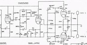
I want to build a clone of the Alembic F2-B starting from the schematic on this site. http://moosapotamus.net/IDEAS/F2B/alembic.htm
The only difference being that I only want one channel. I should mention I'm a newbie in electronics, not totally though, I've done some soldering of PCB kits before and such. A friend of mine who's an engineer will also help.
So here's my questions
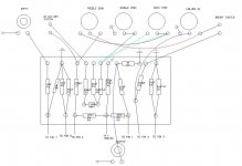
I've drawn up an eyelet board for the placing of the components, can one of you guys be so kind as to check out this next to the schem and telll me if I did it ok? I'm not sure I got all the switches and pots with the right lugs. Look at the drawing of my pots like you would be directly looking at the back of the pot. Also, I had no idea how to draw a switch and for that matter what sort of switch to use.
This is only the drawing of the channel. My friend and I still need to figure out the power section.
Attachments
Hint, Hint. Look at the schematic of the Black Face Fender Twin-Reverb. That's the one Garcia gave to Turner to build the prototype. Somebody out there is making good quality G10 glass boards with brass turrets for the old fender amps. Save yourself a ton of work and buy one.
Thanks very much for the hint. I had read the circuit was based on a blackface dual showman so I went and checked out a bunch of Fender circuits. The F-2B's channels are obviously Fender tone stacks, no doubt about that and it is indeed almost identical to the vibrato channel of the blackface twin reverb besides one or two cap values.
I doubt I'll find a pre-built layout exactly like that but at least now I can compare my layout to the Fender ones available.
I doubt I'll find a pre-built layout exactly like that but at least now I can compare my layout to the Fender ones available.
Thanks very much for the links, I won't find something pre-made since I'm only building a preamp but now I know where you find the glass boards and the turrets for when I build it.  I like to do it all myself anyway, I feel like I'm cheating if I buy a turret board or populated board from someone else
So does anyone have a second to see if my layout will work or if I screwed up? I'd be eternaly grateful to anyone who does
So does anyone have a second to see if my layout will work or if I screwed up? I'd be eternaly grateful to anyone who does
The schematic referenced has an error in the tone stack. There is a node on the 100k and 250pf at top. The 680pf is paralleled with the 250 to shift the treble point. There are several photos of the F-2B on the net showing controls and switches. While your basic eyelet layout (with the above correction) would work, it looks potentially noisey and very messy with too many runs from the controls to the board and the treble boost and shift caps should be close to controls and not on the board. Again find photos of the alembic's internals as well as other guitar heads and emulate the layout and ground paths. There are turrent board versions of Princetons that can easily fit your needs. I have fun building preamps for myself all the time, one or two different each year. It's easy, but tricky and if you're a rookie with tubes, read up on safety or build a fet version 
I have it directly from Mica Wickersham that the F2-B is a straight derivative of the old Fender front end. There's no debate there. The "F" in the name is a hint if you want to think along those lines. Add an effects loop and a simple crossover and you're done.
I own one, myself. It makes a nifty front end for a Hafler P-500.
Grey
I own one, myself. It makes a nifty front end for a Hafler P-500.
Grey
So scottnixon what you are saying is that where the line from R4 to C3 crosses the line from C2 to R5 there should be a connection between the two?!
I have just finished my layout and are about to order the electronic parts so this is vital information.
I plan only to make a single channel preamp but with the same circuit as Phill found on moosapotamus.
He has a good power supply compared to the original.
I just can't wait to finish this project!
Thanks
The 'hi cut' on the referenced schematic is more of a treble shift than a cut. Deep switch on a Bassman 135 can be found here: http://www.schematicx.com/schematic/fender-bassman-135-amplifier-schematic/
I am sorry for hi-jacking your thread, Phil.
But since we are rocking the same boat and both using the same schematics, this might be of mutual benefit ;-)
I'll stop if you think I'm taking it too far.
I see the similarities of the tonestack of the Bassman 135, the Dual Showman and the Alembic (moosapotamus).
Only two things differs. The hi-cut capacitor and the size of the mid pot.
The hi-cut obviously didn't have the effect I thought it would. I was looking for a deep boost like the one on the Bassman.
The guy at moosapotamus had changed the mid pot value from 10k to 250k.
If it is not a mistake, what difference does it make?
Thanks ken.berg.
I've just being fooling around with Tone Stack Calculator.
It looks like the higher mid pot value kills the bass and treble control (less than 5 dB).
Stick to 10k linear!
I think that the James stack and especially the Bench stack looks very smooth and versatile compared to the ordinairy Fender stack.
Wow, I'm surprised there was all this activity on the thread and I totally missed it! 
I had to take a break from the project because of other projects in progress.
Nordskov, I'd love to make this thread a decent F2-B build thread! If you want to post what you've got so far would be great for the both of us to help us through this build. My build will probably go a little slower than yours though. I plan on posting pics when I start building it, I'd love to see pics of yours too.
What voltage are you using in your country? I'm on 240v @ 50hz, I stil need to have the power supply designed for me, a friend would do it but unfortunately isn't going that fast on it and I don't want to bother him too much.
Download PSUD2 from Duncan Amps and have a go yourself. It's not that hard and it has enough standard parts in it's list to do the job. It's always worked out within a couple of percent in reality from the sim if I use the correct specs for the parts.phil mailloux said:I stil need to have the power supply designed for me, a friend would do it but unfortunately isn't going that fast on it and I don't want to bother him too much.
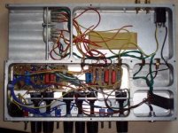
This is just the preamp without power-supply of course. I have taken out the ECC83 because I'm going to clean it up. It's a bit of a rats nest, too small a housing I suppose. The extra two pots on the left were for a switchable tube overdrive, but I couldn''t get it to work so I took it out.
This F2B bit has got a bit of a twist, it's got a switchable "high" capacitor a-la Mesa Bass 400 and also the "Bass-shift" function, as well as the bright switch.
The powersupply is still a bunch of components on a plank, quite scary, considering the fact I had some 330uF/ 450volts capacitors lying around and used three of them...
I used two 12volts transformers back to back, and I think my anode voltage ended up being a bit higher than the specced 300 for the original F2B, I think something like 325volts.
regards and good luck with your builds!,
Jarno.
Attachments
It looks good, I love that sort of point to point wiring 
My project has stalled a bit since I don't have a power suply for it yet and have no idea how to design one. If you get yours to work would you mind showing me a schem of your power supply? It would be helpful since we're both running from 220-230v mains.
Is the preamp schematic the modified version that you used or the original?
I'd love to see the final product when you finish with it.
- Status
- This old topic is closed. If you want to reopen this topic, contact a moderator using the "Report Post" button.
- Home
- Live Sound
- Instruments and Amps
- Alembic F2-B


