Hello Phil,
Well, if you like point to point wiring, you'll love the way I did the powersupply!
It's somewhat dangerous I suppose, and the "free hand in your pocket" rule is definitely appropriate.
All of these power supply schematics are similar, and I used what I had around, so I used the original schematic mainly for the anode voltage, but I think I got this from the Alembic documentation, not sure anymore it's been a while.
Just use two transformers with the secondaries together, but you being at 240 I think you'll end up quite high (1,4x240=336volt), maybe you could use a 12 volt and 9volt transformer, to lower the voltage a bit.
For the filament voltage I used a bog standard three legged regulator to put out 12 volts, but I lifted that voltage slightly by using a diode on one of it's legs, I ended up with something like 12,6 volts and used two filaments in series. I think, but I'm not sure, you can't do this with all types of valve 12AX7 and ECC83 are different.
I'll make a schematic and a photograph later today, I am at work right now.
Best regards,
Jarno.
PSU Kits
Hey Guys, I'm currently in the assembly stage of my own F2-B preamp build, and I found a PSU kit that works very nicely if you're not fully confident working with HV supplies (and if you're not, you shouldn't be.. it can be quite a shocking experience!)
This supply provides enough juice to run six 12A_7 tubes (AT7s, AU7s, or AX7s, etc...) and has selectable 6.3V or 12V heater outputs. Main output is spec'ed in the schematics at 320V @37mA. Comes with all the small components (caps, single diodes, resistors)and PCB, you'd need to get the power transformers (Hammond 229B16 and 229B230 I believe) and a 35mm SIP bridge rectifier.
Cool thing is that everything is low profile and it fits nicely into a 1U project box, but its a bit pricey ($150 for the kit, transformers will run another $15 apiece, I managed to scavenge a BR from an old computer PSU) but all the work is done for you.
ONE THING: I found that the PCB outputs for the heater are not +Vcc and Gnd, they're actually +Vcc and -Vcc. So if you connect the heaters, make sure you use your chassis ground, or else you'll send 24V across the filaments (if you run the heaters in series @ the 12V setting). Another way around this is to use the 6.3V setting, which will give you 12V across both points, if you don't want to run to chassis ground.
http://www.londonpower.com/catalog/product_info.php?cPath=15&products_id=62
Re: PSU Kits
That will deal with 6 X and probably T, but not U.mtyndorf said:This supply provides enough juice to run six 12A_7 tubes (AT7s, AU7s, or AX7s, etc...) and has selectable 6.3V or 12V heater outputs. Main output is spec'ed in the schematics at 320V @37mA.
Oh it's been a long time since I've been here. I thought this tread was long dead.
Sorry, Phil, for not replying to you post.
I'm done with the preamp, but I ran into some difficulties. Actually they are still there
🙄
I have a problem with severe feedback in my tonestack.
I did try to disconnect it by make a short between the two stages via a 0.1 uF capacitor.
That did the trick, but I can't find any irregularities with the wiring.
I have been over it a zillion times and everything seems to be connected like in the schematics. No shorts, no nothing.
Does anyone have an idea?
I plugged it into the effect return on my GK1001RB-II, but man... the signal is very weak.
I have to turn the master vol past 12 to get a decent SPL.
Could it be due to a mismatch in input or output impedance? I play a Sandberg bass with preamp.
Would it help if I put some kind of an opamp before the first stage?
I did the PSU with two toroid trannies back-to-back. I took the 12V from #1 secondairy and app. 315V from #2 primairy. We run 230V in Denmark.
I haven' installed a bleeder resistor after the electrolytics, - yet.
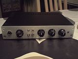
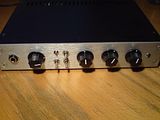
It fits very fine in a 1 unit box, 23 cm wide and 17 cm deep.
I will post a picture in near future 😎
I haven' installed a bleeder resistor after the electrolytics, - yet.
It fits very fine in a 1 unit box, 23 cm wide and 17 cm deep.
I will post a picture in near future 😎
Here are some pics:
 The capacitor sticking up on the left is bypassing the tonestack. And so is the unsoldered resistor.
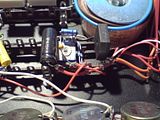 The low voltage supply uses a LM317 regulator (out of image to the right).
 The blue ON-led is missing in the righthand socket.
 The capacitor sticking up on the left is bypassing the tonestack. And so is the unsoldered resistor.
 The low voltage supply uses a LM317 regulator (out of image to the right).
 The blue ON-led is missing in the righthand socket.
Looks great, that's a very nice case, love the cute toroids as well. What's the VA rating on those?
I really should finish mine one of these days, too many other projects!
Best regards,
Jarno.
I really should finish mine one of these days, too many other projects!
Best regards,
Jarno.
Almost there...?
Hey guys, maybe one of you would be able to help me nail down this issue... as far as I can tell, the circuit is wired right, but I'm getting some interesting results here...
Now audio does get from one end of the circuit to the other, tone controls do have an effect as well as volume, however the noise floor is pretty high, but it does something a little weird. I'll hit a note on the bass and it comes through strong, albeit a bit dirty, and as it decays the noise floor will start increasing in volume until there's a steady hum.
I'm thinking its a ground loop somewhere, or maybe AC getting into the plate supply? I'm going to put a larger AC filter cap on B+ (the cap is spec'ed at 22uF/350V, but my supply is putting out 380V due to a hotter-than-normal AC wall output.. around 123 volts). I have a 47uF/400V cap I'm going to try out.
Everything is tied to a common ground (on the AC line itself for testing purposes since its in and out of a metal box often). Should I chassis ground the AC and tie the tube grounds to it on their own, seperate from the signal/tonestack grounds?
It works... but it doesn't. Any thoughts?
Thanks!
Re: Almost there...?
could be to much plate voltage for the tube.
could be to much plate voltage for the tube.
mtyndorf said:Hey guys, maybe one of you would be able to help me nail down this issue... as far as I can tell, the circuit is wired right, but I'm getting some interesting results here...
Now audio does get from one end of the circuit to the other, tone controls do have an effect as well as volume, however the noise floor is pretty high, but it does something a little weird. I'll hit a note on the bass and it comes through strong, albeit a bit dirty, and as it decays the noise floor will start increasing in volume until there's a steady hum.
I'm thinking its a ground loop somewhere, or maybe AC getting into the plate supply? I'm going to put a larger AC filter cap on B+ (the cap is spec'ed at 22uF/350V, but my supply is putting out 380V due to a hotter-than-normal AC wall output.. around 123 volts). I have a 47uF/400V cap I'm going to try out.
Everything is tied to a common ground (on the AC line itself for testing purposes since its in and out of a metal box often). Should I chassis ground the AC and tie the tube grounds to it on their own, seperate from the signal/tonestack grounds?
It works... but it doesn't. Any thoughts?
Thanks!
Don't know the F2 circuit but I remember the Alembic preamps as being a standard Fender front end with a voltage doubler for power. Is that the item ?
I've built a severa; of these and eventualy worked out pcb that I now use. Never any hum problem even with everything out of the box.
Here's a short diy:
http://www7.taosnet.com/f10/fender_pre.htm
Frank
I've built a severa; of these and eventualy worked out pcb that I now use. Never any hum problem even with everything out of the box.
Here's a short diy:
http://www7.taosnet.com/f10/fender_pre.htm
Frank
Toroid rating
@ Jarno
The toroids are from Talema and are rated at 15W. Someone stated his stereo F2-B was drawing 5W, so I assumed a 15W supply would be sufficient for mono.
The chassis is from HiFi 2000 in Italy:
http://www.hifi2000.it/default.asp?id=106&mnu=106
Nice chassis at a reasonable price.
@ Deepthrob
That is the exact schematic I've used, except from the fixed mid resistor in the tonestack. I use a 10k lin. pot. as suggested.
@ mtyndorf
+1 for the excessive voltage. If you look at Deeptrobs link the plate voltage should be within 150-250V. You are running at 380V, more than 50% too high. Ouch
As I wrote previously, the output is very low. Could it be due to an impedance mismatch?
If so, how should I deal with it?
Nordskov
Have you tried to pinpoint the location where you lose the signal?
I was going to type that preamps usually have a cathode follower with less than unity gain, but I now realise this one doesn't so that can't be the culprit.
Voltages are all ok, I assume? Have you checked the values of the resistors top and bottom?
Best regards,
Jarno.
Edit:
Could be impedance mismatch, as the F2B has a very high output impedance, and Alembic advises to use only short interconnects to the power amp. My ADA power amp has only 50k input impedance (which I think is very low), can you put something in between, like a effectpedal or buffer?
Re: Toroid rating
If use raised the plate voltage in the tube above the specs for the input circut you would also need a higher amount of gain current for the input side of the tube. Bring the voltage to the tube plate down and see if that helps.
If use raised the plate voltage in the tube above the specs for the input circut you would also need a higher amount of gain current for the input side of the tube. Bring the voltage to the tube plate down and see if that helps.
Nordskov said:@ Jarno
The toroids are from Talema and are rated at 15W. Someone stated his stereo F2-B was drawing 5W, so I assumed a 15W supply would be sufficient for mono.
The chassis is from HiFi 2000 in Italy:
http://www.hifi2000.it/default.asp?id=106&mnu=106
Nice chassis at a reasonable price.
@ Deepthrob
That is the exact schematic I've used, except from the fixed mid resistor in the tonestack. I use a 10k lin. pot. as suggested.
@ mtyndorf
+1 for the excessive voltage. If you look at Deeptrobs link the plate voltage should be within 150-250V. You are running at 380V, more than 50% too high. Ouch
As I wrote previously, the output is very low. Could it be due to an impedance mismatch?
If so, how should I deal with it?
Nordskov
Low power
Hi Jarno.
I have the tube running at 218 V on the plates and 6.3 V on the fillament. That's okay.
I don't recall the rest of the voltages and my multimeter just disintegrated 🙁
I am leaning towards the mismatch issue. The impedance of the Effect Return on my GK1001-RBII is 50kOhm too.
I did use a short cord (1.0 m) when testing. That doesn't seem to be the problem.
How about adding a permanent buffer to the output, as you suggested - but not just a pedal?
What would be an appropreate easy-to-mount-in-the-box schematic?
But first of all I have to pinpoint the cause of the feedback in the tonestack.
Regards,
Nordskov
Re: Low power
try bring the plate down to say 150 volts. The feedback could be do to plate saturation and the bleed over from the plate being oversaturated. Could also be there is to low of a impednece somwhere bringing plate current down to the input circut.
try bring the plate down to say 150 volts. The feedback could be do to plate saturation and the bleed over from the plate being oversaturated. Could also be there is to low of a impednece somwhere bringing plate current down to the input circut.
Nordskov said:Hi Jarno.
I have the tube running at 218 V on the plates and 6.3 V on the fillament. That's okay.
I don't recall the rest of the voltages and my multimeter just disintegrated 🙁
I am leaning towards the mismatch issue. The impedance of the Effect Return on my GK1001-RBII is 50kOhm too.
I did use a short cord (1.0 m) when testing. That doesn't seem to be the problem.
How about adding a permanent buffer to the output, as you suggested - but not just a pedal?
What would be an appropreate easy-to-mount-in-the-box schematic?
But first of all I have to pinpoint the cause of the feedback in the tonestack.
Regards,
Nordskov
Hi Kramerguy.
You're a lot faster on the trigger than others in this tread.
No offense to the rest of you guys 😉
Sorry if I didn't make this clear.
The feedback disappeared when I bypassed the tonestack via a 0.1 uF capacitor.
So the fault is not within the tube circuit.
As I revisited my schematics, I realized that my memory is marked by my +30 years 🙄
I don't recall the plate voltage.
The 218V was actually 318V for the B+ as stated on this schematic, which is the one I used (except I left out C8 22uF/350V), together with the PSU schematic:
http://moosapotamus.net/IDEAS/F2B/alembic.htm
I guess the plate voltage can be roughly calculated, but not by me 😀
I will return with a proper set of voltage measurements, when I get my multimeter fixed.
Regards,
Nordskov
My multimeter is up and running again, so here are some fresh voltage measurements.
All components refer to this schematic:
http://moosapotamus.net/IDEAS/F2B/alembic.htm
B+ = 288V
First triode:
R4 voltage drop = 90V
R3 voltage drop = 1.4V
Second triode:
R8 voltage drop = 0.0V!!!! This is new.
R7 voltage drop = 0.0V Of course.
I have measured the resistance of R8 = 99.5kOhm. I have tried two different tubes. What is going on?!
I am building two identical amps, the other has full reading.
(The second amp is not fully assembled, tonestack is not connected)
B+ = 280V
First triode:
R4 = 87V
R3 = 1.4V
Second triode:
R8 = 113V Shouldn't it match the first triode?
R3 = 1.8V do
I'm a bit puzzled here. Can someone help me?
Regards,
Nordskov
I have passed this onto my grandfather who was a tube designer at both RCA and westinghous in the 40-60's and he did all manner of broadcast and reciver tube. He has been rather ill lately as he is approaching 85+ yrs of age but He did take an interest in your problem. If he gets back to me I will let you know what he has to say about the design and any potential problems you are having.
To say he has forgotten more about tubes then most will ever know is a mild understatement. He probobaly designed a few of the common power tubes use in many things these days or had a hand in them.
I wish I could get him to somehow download his knowledge into my brain so it would not be lost but alas I did not take up electronics engineering as an occupation.
Nordskov said:My multimeter is up and running again, so here are some fresh voltage measurements.
All components refer to this schematic:
http://moosapotamus.net/IDEAS/F2B/alembic.htm
B+ = 288V
First triode:
R4 voltage drop = 90V
R3 voltage drop = 1.4V
Second triode:
R8 voltage drop = 0.0V!!!! This is new.
R7 voltage drop = 0.0V Of course.
I have measured the resistance of R8 = 99.5kOhm. I have tried two different tubes. What is going on?!
I am building two identical amps, the other has full reading.
(The second amp is not fully assembled, tonestack is not connected)
B+ = 280V
First triode:
R4 = 87V
R3 = 1.4V
Second triode:
R8 = 113V Shouldn't it match the first triode?
R3 = 1.8V do
I'm a bit puzzled here. Can someone help me?
Regards,
Nordskov
Need Help-Newb
I am hoping to clone my Kern IP-777 one day. Is there anyone out there that can help me get information about acquiring the schematic?
I am hoping to clone my Kern IP-777 one day. Is there anyone out there that can help me get information about acquiring the schematic?
- Status
- Not open for further replies.
- Home
- Live Sound
- Instruments and Amps
- Alembic F2-B