http://www.diyaudio.com/forums/solid-state/1429-pi-filter.html?perpage=15&pagenumber=1 . I used a pair in a Aleph 30 they must be sized fairly large mine ran quite hot. After that economics has pointed to resisters.
Bill
Bill
Generally speaking, Aleph and First Watt amps are not especially suited for faulty loudspeaker designs... 😉
Will the Aleph j-x drive a 1 ohm load ?
Unlikely, but it is hard to give a definitive answer.
It will also depend on how efficient your speakers are and how loud you like to listen to music.
eg If you had 100dB/W/m speakers, then you probably wouldn't have a problem.
However you most likely have 90dB/W/m speakers which will be a problem.
Last edited:
I am seriously considering a standby mode for this amp.
Has anyone done this before?
I want to drop it down to about 10Watts dissipation in standby mode.
Any advice on the best/simplest way to do this would be appreciated.
Thanks
Has anyone done this before?
I want to drop it down to about 10Watts dissipation in standby mode.
Any advice on the best/simplest way to do this would be appreciated.
Thanks
Hello,
I'm completely new to this forum but have been searching and reading her for a couple of months now. Great stuff !!!
Here"s my question: has anyone allready finished an Aleph-jx and if so is there anyone who could report on some results?
Are there still pcb's available from the groupbuy or is there perhaps someone who has left-over pcb's. My intention is go for the x option. so that would mean 4 aleph-j boards , two x-boards (and power supplyboards)
Thanks in advance
Timo
Please tell me , to Aleph JX what values are P1 and RP?
In alternate current source when using the J74 - C4, Z1, R8, R5 are used?
Which is scheme to connect the J74's?
Thanks!
In alternate current source when using the J74 - C4, Z1, R8, R5 are used?
Which is scheme to connect the J74's?
Thanks!
Generally speaking, Aleph and First Watt amps are not especially suited for faulty loudspeaker designs... 😉
OK.. Works best on pam-pam speakers ......................... 😀
Unlikely, but it is hard to give a definitive answer.
It will also depend on how efficient your speakers are and how loud you like to listen to music.
eg If you had 100dB/W/m speakers, then you probably wouldn't have a problem.
However you most likely have 90dB/W/m speakers which will be a problem.
Thanks for the response , my search continues ........ 🙂
Thanks for the response , my search continues ........ 🙂
It doesn't mean you can't get it to work with low impedance speakers. It just means you will need to increase the bias a lot more and you will need bigger heatsinks.
I have 4Ohm speakers so I have to diverge from the original design slightly ie use three pairs of mosfets at the output, increase the bias, and use nice big heatsinks.
Having said that if you have problematic speakers then an F5 would probably be the best amp to use.
Hello thanh1973,
Thanks for the response and putting things into a better perspective for me. So you are saying i would be able to use the AlephJ-X topology if i was to add more outputs and of course the appropriate size heatsinks ?
Would 8 Prs /ch suffice ? I would think an increase in the driver stage also ?
How would you rate the sound of the Aleph vs what others have built here ?
regards,
Last edited:
I would think an increase in the driver stage also ?
This is where the problem lies with 2SJ109 or dual 2SJ74, it doesn't have enough drive on its own for that many outputs. You would have to cascode the inputs, which isn't easy with PD boards. Not to say you can't go about and do it, I could be wrong, but you may run into distortion issues.
-john
Last edited:
To avoid any confusion these comments refer to the standard Aleph J not the JX.
MEGA-amp is right, but you should have no problems with 3 pairs.
You could safely bias each mosfet at 2 A which will give you a total bias current of 6A.
This will be around 300W of heat dissipation per channel. However you could drop the voltage to +/-20V for around 240W of heat per channel.
So you are going to have to do monoblocks and the heatsinks are going to be BIG.
If you don't mind the heat dissipation then go for it.
Last edited:
Well, I like pictures 😀
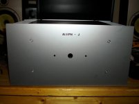
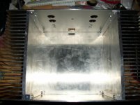
I finished the rough assembly of my Aleph J enclosure and I wanted to share some pictures of it. I still need to finish the top panel, drill and tap holes for the fets and holes in the bottom panel for the power supply and transformer.
I'm wondering if I need to add ventilation holes in the top and bottom cover?
Attachments
Very nice! Can you describe how you did the front and rear panels with such nice cutting and finishing?Well, I like pictures 😀
I finished the rough assembly of my Aleph J enclosure and I wanted to share some pictures of it. I still need to finish the top panel, drill and tap holes for the fets and holes in the bottom panel for the power supply and transformer.
I'm wondering if I need to add ventilation holes in the top and bottom cover?
I would add a few holes top and bottom. I used perf material on the top of mine.
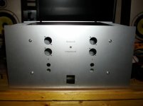
Is that 4 XLR openings and no holes for AC power inlet or fusing

Tom
Thanks!
The front and rear panels are from Front Panel Express. I'm going to be using Neutrik D series jacks for both the XLR and RCA, so they have the same bolt pattern, the lower pair will be the RCA's. The IEC socket I'm using has an integrated fuse holder so no extra hole for that.
I like having my power switch on the front, so I'm going to use a latching Bulgin vandal resistant pushbutton mounted on the front, it's only rated for 3A/250VAC so I was a little concerned with long term reliability and will be using it to activate a 30A DPST relay.
I might try taking the top panel to a local machine shop to see if they can rout some nice looking cooling slots in it, I don't have anything that can slot cut 1/8" aluminum. Drilling all the holes for this really makes me want a drill press, doing it all with a hand drill kinda sucks haha 😛
Thanks!
The front and rear panels are from Front Panel Express. I'm going to be using Neutrik D series jacks for both the XLR and RCA, so they have the same bolt pattern, the lower pair will be the RCA's. The IEC socket I'm using has an integrated fuse holder so no extra hole for that.
I like having my power switch on the front, so I'm going to use a latching Bulgin vandal resistant pushbutton mounted on the front, it's only rated for 3A/250VAC so I was a little concerned with long term reliability and will be using it to activate a 30A DPST relay.
I might try taking the top panel to a local machine shop to see if they can rout some nice looking cooling slots in it, I don't have anything that can slot cut 1/8" aluminum. Drilling all the holes for this really makes me want a drill press, doing it all with a hand drill kinda sucks haha 😛
Sounds like a great plan. I've always wanted to try FPE but didn't have confidence in things like real world clearances and such to use their application and pull the trigger.
I bought a fairly inexpensive Delta press at Lowe's. That and a step bit will do wonders. I did break down and get a Greenlee punch for XLR's though.
Good luck with the build!
Corey,
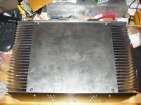
Where did you buy your heatsinks? What is the thickness and fin height?
Looks great! 😎
The heatsinks are from barredboss on ebay, aka HeatsinkUSA. The base is 3/8" thick and the fins are 2" high, 10.125" total width. I got 2 8" long sections from him.
This is where the problem lies with 2SJ109 or dual 2SJ74, it doesn't have enough drive on its own for that many outputs. You would have to cascode the inputs, which isn't easy with PD boards. Not to say you can't go about and do it, I could be wrong, but you may run into distortion issues.
-john
what about doubling the driver stage ?
- Home
- Amplifiers
- Pass Labs
- Aleph J-X Amp Project