Thanks Bill,
I haven't connected up this bias config yet but in my existing config (which uses a DC blocking cap on amp input) I used 1:1 and 1:2 seems a lot louder, which is to be expected, I guess.
Any idea on the 2K across the primary & why it was suggested?
This trafo datasheet says
I haven't connected up this bias config yet but in my existing config (which uses a DC blocking cap on amp input) I used 1:1 and 1:2 seems a lot louder, which is to be expected, I guess.
Any idea on the 2K across the primary & why it was suggested?
This trafo datasheet says
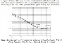
And it specifies optimum source impedance of minus 18 ohm, so what exactly does this mean if working with a higher source impedance? A higher LF drop-off? Any effects at HF?The LL1517 has sufficient low copper resistance to meet broadcast specifications in a conventional drive configuration, but is (as all output transformers) ideally used with mixed feedback drive circuits. (See separate paper for mixed feedback design principles).
I'm interested to see what you come up with for the the t-amp connection, I've got a couple of tripath based amps here that I would like to connect to my UTC A-20 coupled DAC without caps.
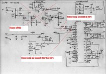
Vaughan, the schematics on the previous page are the wiring configuration for the Tripath connection - just use the lead from the secondary of the transformer that went to the amp's ground and re-direct it to the Biascap pin (pin 14 for the TA2020) after having disconnected this pin form ground.
Now the secondary wire that went to the amps input signal lead still connects there but all DC blocking capacitors are removed.
Diagram attached
Now the secondary wire that went to the amps input signal lead still connects there but all DC blocking capacitors are removed.
Diagram attached
Attachments
Please excuse if this is a stupid question. I've got the UTA a-20's all set to connect to the DAC output and the caps have been removed. But for each output (R+,R-,L+,L-), there are 2 holes/pads. Yet I see everyone connecting w/ only 4 wires.
Which pad do I solder to? the shaded/striped pad? Or is there a step I'm missing?
Use the pads that are closest to the dac chip, the other pads go to the opamps.
Best, Bill
Thanks Bill,
I haven't connected up this bias config yet but in my existing config (which uses a DC blocking cap on amp input) I used 1:1 and 1:2 seems a lot louder, which is to be expected, I guess.
Any idea on the 2K across the primary & why it was suggested?
This trafo datasheet says
And it specifies optimum source impedance of minus 18 ohm, so what exactly does this mean if working with a higher source impedance? A higher LF drop-off? Any effects at HF?
What it means actually makes my head hurt, because I am a minimalist at heart.
Supposedly OP trafos work best in an active opamp based feedback oriented circuit that I detest on basic principles. I can't talk about it because my head might explode.😀
The trafo likes the 2k load across it, but the chip doesnt. The 1k on each leg plus the 100ohms of the chip looks just like 2.1k to the trafo, and the chip sees a load it can handle. With the trafo connected directly, the chip sees a 9ohm dc load, and that cant be good for a Vout dac chip. Not rocket science on my part, just good logic.
Maybe this is a better configuration that doesn't reverse Primary & secondary use. So primary goes to DAC & secondary goes to AMP
Havoc08, hope this helps?
Thank you jkeny. My problem is that I'm a big electronics enthusiast, but have no education in the field other than many years of reading on the web. Just recently found diyaudio (~2 years) so am just beginning to learn 🙂.
Vaughan, the schematics on the previous page are the wiring configuration for the Tripath connection - just use the lead from the secondary of the transformer that went to the amp's ground and re-direct it to the Biascap pin (pin 14 for the TA2020) after having disconnected this pin form ground.
Now the secondary wire that went to the amps input signal lead still connects there but all DC blocking capacitors are removed.
Diagram attached
I'll have to find the same pin on other chips I gather (have some TAA4100 41hz amp 9, an amp 10, several amp 3's and a multitude of ta2024 and 2050 amps from sure electronics)?
I'm going to build a shigaclone and would like to use this dac with it, preferably with the transformer upgrade as everyone seems to think it is way better than any opamp version?
It's getting coupled to a TAA4100 which drives a 2.1 system via an active crossover.
What is the bias voltage and what does the bias cap pin do?
Sorry wrong diagram for bias configuration in above post - here's the correct one
Another question... is one LL1517 enough for stereo signal if I use 1:1?
Also does the 1:1 or 1:2 depend on the Vout of the DAC and the gain setting of the amp compared to the max Vin of the amp?
What it means actually makes my head hurt, because I am a minimalist at heart.
Supposedly OP trafos work best in an active opamp based feedback oriented circuit that I detest on basic principles. I can't talk about it because my head might explode.😀
The trafo likes the 2k load across it, but the chip doesnt. The 1k on each leg plus the 100ohms of the chip looks just like 2.1k to the trafo, and the chip sees a load it can handle. With the trafo connected directly, the chip sees a 9ohm dc load, and that cant be good for a Vout dac chip. Not rocket science on my part, just good logic.
Thanks Bill,
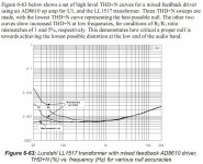
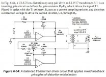
I looked into the op-amp based mixed feedback circuit you referred to & I agree, in principle, it adds back in an op-amp which is one of the devices that the pure trafo approach avoids. Still, I'm intrigued by the reduction in LF THD & the flat thd across the freq range - just might give it a try to satisfy my curiousity.
Attachments

It's pin 5 on the TAA4100I'll have to find the same pin on other chips I gather (have some TAA4100 41hz amp 9, an amp 10, several amp 3's and a multitude of ta2024 and 2050 amps from sure electronics)?
The 2.5V bias is generated internally by the chip & it is needed for it's operation.What is the bias voltage and what does the bias cap pin do?
Two LL1517s are needed for stereo operation.
Yes, all that you say is correct. There may be other minor factors that determine whether 1:1 or 1:2 are better - DCR, etcAlso does the 1:1 or 1:2 depend on the Vout of the DAC and the gain setting of the amp compared to the max Vin of the amp?
Today 12:48 PM
And here's the circuit & it's thd plot attached.
All of this comes from an interesting pdf called "Op Amp Applications" by (the famous) Walter G Jung
Nothing wrong with trying it, but maintain your perspective, numbers are just numbers. The entire distortion spectrum is more important than a total. Keep in mind the inherent distortion of a speaker at low frequencies is generally very high, some approaching 10%.
jkeny
So 11 and 12 cant be used with 4 and 6 for one channel leaving the other side of the pins for the 2nd channel if you do 1:1 and not 1:2 as you have shown?
edit:
Think I get it. Theres 2 primaries and 2 secondaries which allows 1:1, 1:2, 2:1 and 2:2 (same as 1:1) but it has to be the same mono signal?
Last edited:
BTW jkeny could you compare the lundahls to the stock DAC and/or different opamps and transformers you might have tried?
found this and thought it might be of interest jkeny http://img183.imageshack.us/img183/151/tda1541.jpg
He was asking for input about whether it was correct what he had done, but he also uses a opamp before the lundahls to deliver the low ohms the tranny likes.
He was asking for input about whether it was correct what he had done, but he also uses a opamp before the lundahls to deliver the low ohms the tranny likes.
found this and thought it might be of interest jkeny http://img183.imageshack.us/img183/151/tda1541.jpg
He was asking for input about whether it was correct what he had done, but he also uses a opamp before the lundahls to deliver the low ohms the tranny likes.
Thanks - he's using the OPA660 transconductance op-amps as IV converters before the transformer - I don't think this is mixed feedback as in the schematic I posted.
I can't revert back to the op-amp o/p stage easily to compare(it involves some smd soldering & I'm reluctant to do so at this stage) & the Slagle trafo is the only other one I have so far. Oh I did try a Talema toroidal mains trafo on it but sound from it was rolled off in the top & bottom AFAIR.
Bill, I agree about thd not telling the full story (or even a small percentage of the story) but a flat thd across the full freq spectrum hints at a desirable thing, I believe, as long as it's achieved in a simple way - the nickel transformers come to mind! We'll see how the op-amp sounds in this regard!
Last edited:
oh.. okay.. Just saw this schematic and thought it looked similar to what you posted 🙂
How do you think the stock dac sounds compared to the lundahl upgrade.. is it worth the effort and money?
How do you think the stock dac sounds compared to the lundahl upgrade.. is it worth the effort and money?
How do you think the stock dac sounds compared to the lundahl upgrade.. is it worth the effort and money?
I'm not sure as I find relying on audio memory notoriously unreliable, for me anyway. I remember the shock of the difference in sound between the stock op-amp o/p stage & the Slagle trafos. The Lundahl's seem not as good as the Slagle at the moment (in my system,etc) but it might be too early to give an opinion (i guess I just did & that was the caveat 🙂)
This is for Havoc08,
I have done the DC input mod to the Tripath - actually no mod needed to the Tripath. Don't remove the capacitor on the biascap just connect a wire to where it goes to the biascap pin (or connect to the biascap pin itself). This wire will be your pseudo ground and goes to one end of my transformers secondary winding. The other end of the secondary winding goes to the input signal pin. No capacitors needed because both should be at 2.5V potential so no DC, right?
Measure the potential between the two wires before you connect just to make sure they are at the same 2.5V nominally (mine were about 2.4 ish). Connect & check the speaker connectors have no DC on them. It's probably good to have a DC offset circuit & adjust it for 0mV. Mine was at 0mV when I was using caps & went to 10mV when I did this - a slight adjustment & it's back to 0mV.
Well worth it - a slight smear on the highs was removed - obviously from the Wima cap I was using. It's probably a good test rig for testing the transparency of caps too (just thought of that)
I bypassed the vol control also - I'm sure I could have wired it up so no DC was running through it but I wanted to get rid of it anyway - I'm controlling the volume on the PC.
Sorry for hijacking the thread - if we need to talk about this further I'll open another thread!
Use the pads that are closest to the dac chip, the other pads go to the opamps.
Best, Bill
Got it. Many thanks...
- Home
- Source & Line
- Digital Line Level
- Experience with this DIY DAC ?