Guys,
R-core transformers for frontend and power PSUs are the solution, but if there is enough clearance between boards and toroids, that’s fain too.
Well done Sheldon!
Cheers, Mihai
R-core transformers for frontend and power PSUs are the solution, but if there is enough clearance between boards and toroids, that’s fain too.
Well done Sheldon!
Cheers, Mihai
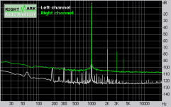
Tuned it up as much as I could by just shifting the transformer some, until I could hear no noise with my ear right at the speaker. Interestingly, the best position was different for the two transformers. Here's the noisier of the two, but still very low by ear. I've got a different layout in mind for the next amp.
Ignore the green curve. Hard to see without expanding the scale, but 2nd harmonic is 100dB down.
Ignore the green curve. Hard to see without expanding the scale, but 2nd harmonic is 100dB down.
Attachments
A whole 10dB improvement from post#851! 12-15dB from #850! And you can't hear it now. That's quite something. Must have translated into more subjective resolution?. It always does for me.
The difference in position is because you null their mutual interference better at some angle between them. You can add some or kill some. Maybe it could work like the way we put coils in passive x-overs. One on its side and perpendicular to each other. Like |---
But then again they would face different to the pcbs. Experimental stuff.
Me I just did as in the pic in a difficult situation when I had a 250VA toroid smack centre under the hood of my small box KT-88 made p2p with all ground returns almost touching it. Gremlin's gone.
Attachments
Salas said:A whole 10dB improvement from post#851! 12-15dB from #850! And you can't hear it now. That's quite something. Must have translated into more subjective resolution?. It always does for me.
The difference in position is because you null their mutual interference better at some angle between them. You can add some or kill some. Maybe it could work like the way we put coils in passive x-overs. One on its side and perpendicular to each other. Like |---
But then again they would face different to the pcbs. Experimental stuff.
Me I just did as in the pic in a difficult situation when I had a 250VA toroid smack centre under the hood of my small box KT-88 made p2p with all ground returns almost touching it. Gremlin's gone.
Might be kidding myself, but I think it does sound a touch more relaxed and open now.
I don't know if it's mutual interference. I tend to think not, and that each transformer is radiating down onto the board beneath it. But I didn't specifically test for it, so I can't be sure. I just tuned each channel in sequence, without cross checking.
Interesting, as I said, that the null is very specific - a matter of maybe 5 degrees rotation, for instance. So I moved and rotated until I hit the null. Then shifted or rotated either side of the null until I could detect hum, and chose the center of those positions.
I might try a shield like yours when I get a chance. Can't hurt.
Sheldon
Well done as always. Enjoy.🙂
What is the sonic fingerprint of that amp BTW? Did you form any picture about it till now?
What is the sonic fingerprint of that amp BTW? Did you form any picture about it till now?
Salas said:What is the sonic fingerprint of that amp BTW? Did you form any picture about it till now?
That's a hard question to answer. After a couple of days, listening to a variety of music, I don't know that the amp has a signature. If I were to say anything, I would have to say it seems completely in control. I don't sense any limitations or strain. I find myself not being aware of the amp, but the music instead. I think tubes have a nice glow, and are easier to work with, but soundwise, I don't know what else I'd ask for. From now on, I'm working on the speakers and the room.
Sheldon
Hi Sheldon,
That was my first impression too. You can listen to the music all day long without developing fatigue. The amplifier is transparent, without sibilance and hash sound, without sloppy bass. The limitations are in the speakers and source, not in the power amplifier.
After many days of listening, I can say that it has a little bit of tube sound, a litle bit of glow
I’m glad you like it!
Cheers,
Mihai
Help please!
Hi Everyone,
I managed to build my first channel of the FC-100 a few months ago but due to lack of time (work and home) the second channel has taken a lot longer than I would have liked. The first channel seems to work very well and is patiently waiting for the second channel so that they can play music together....
Anyway I now have the second channel built and when I tried to set up the bias on the output transistors I couldn't.
On invetsigation the bias voltage going into the base of Q19 is wrong. I have spent some time on this now and I am not getting very far I am sad to say. Once or twice I thought that I had it but no.
So could I ask for your help to debug it please?
The circuit is standard FC-100 using the DIYaudio PCBs. No changes on my part on the PCBs themselves. I have annotated the schematic with voltgaes at various points. The voltages in BLUE are as the LTSpice simulation describes them with a negligible input signal (it doesn't like 0). The voltages in RED are the ones from the second amplifier. If you require any more just ask.
I'd love to hear the two channels playing real music. Hopefully you can help?
Thanks
Attachments

You seem to have several problems
1. the base of the input pair is no where near zero!, so check that the current source is working, so measure the voltage on R19, and double check it's value.
Also check Q2 is operating correctly.
2. Q16 should be clamping the collector voltage of Q21 and Q12(?) to around 34volts so check it's base voltage.
One step further
Hi,
Symon you were right about Q2 (J2) - it was a faulty joint.
Now onto the second problem on the bias.
Thanks
Hi,
Symon you were right about Q2 (J2) - it was a faulty joint.
Now onto the second problem on the bias.
Thanks
Hi Barry
I need you to do some measurements in order to solve the undefined bias issue.
Please find the voltage drop over the following resistors:
R19
R20
R15 R18
R16 R17
Cheers,
Mihai
I need you to do some measurements in order to solve the undefined bias issue.
Please find the voltage drop over the following resistors:
R19
R20
R15 R18
R16 R17
Cheers,
Mihai
Working
Hi Mihai
Thanks for your support. I had the second channel running all afternoon with the bias set. The bias variation across all the six output device was less than 1mv, output offset about 30mV and it was running nice and warm.
I have a little more wiring to do on the preamplifier and then I will be able to (finally) hear the the amplifiers.
How long woud you suggest the run in needs to be?
Well, 30mV offset is a little bit to high for this amplifier. Did you sort the jfets for Idss and how close they've matched?
Output Offset
Hi
Yes I matched the jfets. They were within 0.2 and I went through nearly 200 jfets to get the best pair.
Hi
Yes I matched the jfets. They were within 0.2 and I went through nearly 200 jfets to get the best pair.
Fresh start to the day
I have just realised that the input was not shorted when I took the offset measurement yesterday.
I have just shorted the input and the offset is 19mV.
I have just realised that the input was not shorted when I took the offset measurement yesterday.
I have just shorted the input and the offset is 19mV.
I got 0.2mV (if my memory is right) output offset with matched jFETs.Yes I matched the jfets. They were within 0.2 and I went through nearly 200 jfets to get the best pair.
How did you match your FETs?
Or did you simply measure the Idss?
you haved selected pairs of FETs with the same Idss.
The Fets operate @ ~70% of Idss.
You should take your pairs and find if any match at the actual operating current.
I suspect you will find they are not matched.
Will a pair that does match @ 70% of Idss, still match @ 60% or 50% or 80% of Idss?
The Fets operate @ ~70% of Idss.
You should take your pairs and find if any match at the actual operating current.
I suspect you will find they are not matched.
Will a pair that does match @ 70% of Idss, still match @ 60% or 50% or 80% of Idss?
- Home
- Amplifiers
- Solid State
- RMI-FC100, a single stage audio power amplifier