Hi Paul,
Thanks for the idea.
Are you sure that one can reclock all 3 lines simultaneously using CK without any problem?
I seem to recall trying a single 74HC174 to reclock the 3 lines (just one reclock for each) and having severe clicking noises on the outout. Reclocking just LE solved that problem.
Thanks for the idea.
Are you sure that one can reclock all 3 lines simultaneously using CK without any problem?
I seem to recall trying a single 74HC174 to reclock the 3 lines (just one reclock for each) and having severe clicking noises on the outout. Reclocking just LE solved that problem.
You shouldn't have problems if you are driving 4-6 chips. If your driving anything more than that you'll need to think about buffering the DF clk output - you could do it by using the df to drive 2 gates of a 74HC125 and fan out from the output. If you are running wires to the reclocking chips use a separate wire to each clk input and put something like a 47-100 ohm resistor on each line at the "sender" end.
Hi again Paul,
Don;t mean to labour the point but want to be sure I undertsand your proposal:
Each of the 4 DAC receives 3 inputs.
Are you suggesting that EACH input is reclocked 4 times using a seperate 74HC175 for each, so 12x 74HC175, each wired up so that the signal gets reclocked 4 x?
Sounds like a lot of work!
Also, what would happen if I just reclocked DATA and LE and not BCK?
Yes that would be the best way to go, if you want "deep" reclocking.
Look at the SM5847 and timing diagrams and see what happens if you move LE and data but not BCLK.
Remember that data is clocked into the dac on the rising edge of BCLK. If you shift the data and not BCLK you have a problem. This is the root of problem - you have to respect the timing requirements of the DAC.
If you want a reasonable compromise, cut back to a single flip-flop per line. Just use a single 74HC175 per dac to reclock LE, DATA, and BCLK.
best
Paul
Thanks Paul.
Would it be easier to simply implement your PLL idea? I may not have a good grasp of digital, but I can follow the schematics...could ypu pint me to a suitable one?
Perhaps I'll just settle on the 2-3 times reclocking with '175 as a compromise. This DIY hobby is too time consuming!
Ryan
Would it be easier to simply implement your PLL idea? I may not have a good grasp of digital, but I can follow the schematics...could ypu pint me to a suitable one?
Perhaps I'll just settle on the 2-3 times reclocking with '175 as a compromise. This DIY hobby is too time consuming!
Ryan
Tell me about it 😉
If you want to try out a PLL the simplest thing to do is to use the variant of the Pass D1 PLL I was using initially. It's not ideal but it works pretty well for a small package and is much better than the recovered clock.
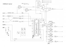
The rev2 schematic on the first page of the thread shows this hooked into the CS8412/SM5842
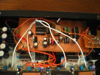
The PLL/VCXO and reclocking circuit comprising U5, U7, U8, U10, U11 and VCXO1 can be built on a bit of perf board.
I put the 2 * 74HC175 onto small perf board adapters which plug into the 74HC86 sockets. These reclock DATA and LE only. BLCK is driven from the output of U10.
If you want to try out a PLL the simplest thing to do is to use the variant of the Pass D1 PLL I was using initially. It's not ideal but it works pretty well for a small package and is much better than the recovered clock.
The rev2 schematic on the first page of the thread shows this hooked into the CS8412/SM5842
The PLL/VCXO and reclocking circuit comprising U5, U7, U8, U10, U11 and VCXO1 can be built on a bit of perf board.
I put the 2 * 74HC175 onto small perf board adapters which plug into the 74HC86 sockets. These reclock DATA and LE only. BLCK is driven from the output of U10.
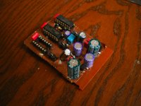
This is the current state of my D1V3 - it's an unholy mess.
It has Jocko's spdif circuit on the far right, a main board with PIC controlled pll and the core of the Tent reclocking circuit, and small board holding the and gate for the reclocking mod, and 74HC175's sitting on adapters.
This is a perfect illustration why I want to get a board designed to hold all this!!
Attachments

I thought I should post my efforts here for the record and benefit of other digital newbies:
In reclocking the signal between the the 5842 and the PCM63, I tried:
1.Reclocking LE (Latch enable) with a 74HC74 flip flop using CK (pin 9 of 5842): Result was ok.
2. Reclocking LE twice (i.e. 1D-1Q to 2D and output from 2Q) using CK on a 74HC175. Better result than single reclocking
3. Reclocking LE 3 times using 74HC374. much louder than 1 or 2 and lots of detail, but noisy spikes at certain parts of the music;
4. Reclock LE 4 times: Worse noise than 3 and louder than 3.
Using 3x reclock on LE, I then reclocked DATA once-still some noise;
Using 3x reclock on LE, I then reclocked DATA TWICE-noise gone on MOST songs, but still present on some music.
Using 2x reclock on LE, I reclocked DATA and BCLK. Using CK of Sm5842, I got nothing but noise; Using an indepedant 11.xxx clock, I got nothing but noise....
So I have settled on just reclocking LE 2x, using 74HC174. Data and BCLK are not touched.
Any feedback welcome.
reclocking
Could anybody give me arguments to reclock many times?
If you enhance the SPDIF in the transport, use a desent VCXO-PLL (or much better: skip them by connecting the masterclock in the transport direct to the DAC) and reclock once, I cannot find any arguments to do this many times.
BTW. I attach the TentLABS reclocking circuit with Paul/Josef's update for the LATCH. I changed also the symbols for U5. In my opinion this is a NOR not an AND.
Attachments
Paosu,
PLease tell me, when you take the clock from the transport, do you have to invert it or put a resistor in series with it?
Also, what do you connect the clock to in the DAC?
Do you have to disable anything in the dac? If so, how?
PAUL:
on the PLL on the first page of this thread, does the VCXO need to be low jitter? Does it need to have a frequency realted to the transport or DAC?
Also, the active part of the PLL is only the 7404, 4046 and 4020 correct? i.e., the only thing you want to accomplish is to get a clean clock to the XTI input of 5842?
The rest of it the '175 and '02 is not needed if I'm not doingthe reclocking correct?
Thanks for any input.
Herb,
WildMonkeySects suggested that deep reclocking of LE had a positive effect on the first page of the thread. The idea seems to be that reclocking multiple times gives a cleaner LE pulse.
WildMonkeySects suggested that deep reclocking of LE had a positive effect on the first page of the thread. The idea seems to be that reclocking multiple times gives a cleaner LE pulse.
Dr. H
Lower jitter is the point of carrying out reclocking, so yes low jitter is the idea. The VCXO needs to be 11.2986Mhz. I'd suggest that the Tent Labs item is your best option. Don't waste your time surfing manufacturers sites, unless you are prepared to purchase in bulk to meet their MOQ's.
The required connections should be on the schematic: The "44.1" input is taken from the CS8412 FSYNC (pin 11). I've pulled the resistor on the BCLK line from the D1V3 board and connected the clock from the reclocking board to the pad closest to the dac. The vcxo clock is fed to the SM5842 using the last pad on the XO side of the CS8412/XO header.
The other signals - LE and DATA are reclocked using '175's on homebrew adapters pluged into the 74HC86 sockets.
So at this level it's a matter of replacing 4 resistor so get back to the standard D1V3 configuration.
cheers
Paul
Thanks Paul,
I am very intrigued by the idea suggested by PAOSU:
Just take the clock from the transport and feed it into XTI (I assume) on SM5842. He says that it is much better than a VCXO PLL...
I assume that trying this idea will entail simply disconnecting the MCK of 8412 from XTI?
Does the transport clock need to be buffered (hc86) or inverted (hc04) before used at XTI?
You'll have to talk to Herb about the details but I don't think you understand how much is actually loaded into that "Just"!! Herb is trying to achieve ultra low jitter figures, and his approach is definitely "no compromise".
Herb, you wrote:
"If you enhance the SPDIF in the transport, use a desent VCXO-PLL (or much better: skip them by connecting the masterclock in the transport direct to the DAC) and reclock once, I cannot find any arguments to do this many times"
Can you please tell us more about feeding the clock from the transport to the DAc?
1. Do you buffer (hc86) the clock?
2. Do you invert it? (hc04)
3. Do you simply connect the clock to XTI on SM5842?
4. I assume that if you do (3), then you have to disconnect the MCK output of CS8412?
I am a digital newbie, thanks for input. !
Ryan
Can I just make a gentle reminder that the thread topic is reclocking PCM63. If you plan to discuss Herb's transport -> dac setup in any kind of detail I'd ask that you start a new thread.
Hi Paul,
Spencer has admitted that trying to use an independant low noise clock to feed XTI on the Sm5842 in the D1V3 does NOT work. Have you found a fix for this, or do you understand why it's not working?
Spencer has admitted that trying to use an independant low noise clock to feed XTI on the Sm5842 in the D1V3 does NOT work. Have you found a fix for this, or do you understand why it's not working?
An answer to Dr H
Dr H.,
I went after Herb's advice - and it is fantastic!!!!!
I am using newly a Tent XO3.2 in the Transport (I have a Marantz CD10, with 11.2986Mhz). The XO3.2 feeds the system clock in the Transport, and is also being used as a SPDIF enhancer, for the DAC (not D1V3 in this case).
This is not all: While it is sending a full SPDIF signal to the DAC's CS8414 receiver (and indeed, this enhanced SPDIF signal is already excellent), there is in addition a second bnc-bnc cable running between the Transport and the DAC: It takes the clean master-clock signal directly from the XO3.2, bypassing the receiver and is being "injected" directly to the XTI (pin 6) of the Digital-Filter.
In this way, there is no need for using the jittery clock recovered by the receiver. You reduce Jitter tremendously and the sound is MUCH MUCH BETTER!
As for the other question - build a Jumper on the receiver, so that you can decide if it shell send the recovery clock to the filter or not (let's say that you have a DAT player, and you want sometime to send the all SPDIF signal through. In such a case simply disconnect the extra clock cable). Now, if you wish to use the direct clean-clock from the transport, you just avoid (through the Jumper) that the recovery clock will go to the filter. In this case, the receiver is responsible for the DATA, but the clock is going separately through the extra bnc-bnc clock-cable, to the filter's XTI.
Simply pay attention to avoid having 2 clock signals running at once. Remember that the enhanced SPDIF is always caring the clock as well.
As Herb says, it is essential to send a clean clock from the transport, before starting the 1X (or 2X or 3X etc, reclocking - yet to be discussed here). In this sense, it can be considered as a part of the needed "steps" for getting good reclocking at the end of the day (i.e. being an "attachment" to this great thread).
Paul Herb, George: My deepest thanks to all of you for this great work here!!!!
Greetings,
IJ.
- Home
- Source & Line
- Digital Source
- Reclocking balanced PCM63