Please stay tuned..
Full review of TU-8800 with Lundahl will be available soon..
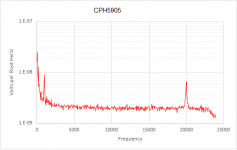
Doctorjohn Cheaptubeaudio: Audio Reviews and More: Elekit TU-8800VK Lundahl Tansformers Tube Rolling TU-8300
Review: Elekit TU-8800 (VK), Part II, Lundahl Transformers, Tube Rolling
Review: Elekit TU-8300, Part II
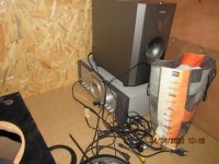
Elekit TU-8800, Part I (has a pic of stock output transformers; tested with LS3/5A)
Elekit TU-8300, Part I
Klipsch Heresy Part III (for system description and general characteristics)
Note: This is a very long article, particularly the section on Tube Rolling. You may want to jump to the section(s) that interest you the most.
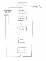
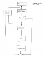
Prologue After I wrote my Elekit TU-8800, Part I, the LTA MicroZOTL arrived and I basically just got deeply immersed for quite a long while. This article is mainly about the detailed tests I am doing now. But in the interim I did re-visit a bit. with YL Horns I did pair it up briefly with my (104 db) YL horns. With the Siemens Top O-Getter 12AT7 and current production Russian "Genalex" KT88, the sound was somewhat too sharp, especially at high volume. This was interesting to me as the same tubes worked very well with my much less efficient (87 db) LS 3/5A's. I took this to mean a little too much power/gain for my horns. 6V6 I then swapped in my RCA 6V6's. Sound audibly improved but was still not entirely satisfactory. I then got diverted by other things. Used as an amp/Gain Issue As I usually have too many sources, I almost always use these Japanese amps (just an amp with a volume knob) as amps, preceded by an active preamp. With Elekit TU-8800, as with my TU-8300, the gain is very high, so the volume knob could not be turned up too much. Even then I encountered a unique problem: occasionally, with a dirty LP, a loud click or pop was enough to trigger the protection circuit of the Elekit, which would then mute itself and the green indicator lamp would partially turn orange red. Turning it off and on again would regain normalcy. This indicated to me again the issue of gain and the amp would better be used as an integrated amp (or as an amp with a passive preamp or TVC). This has happened with my TU-8300 before too.
This unit of TU-8800 is a fully assembled loan unit from vkmusic. I was told it is bone stock except for 2 coupling caps.
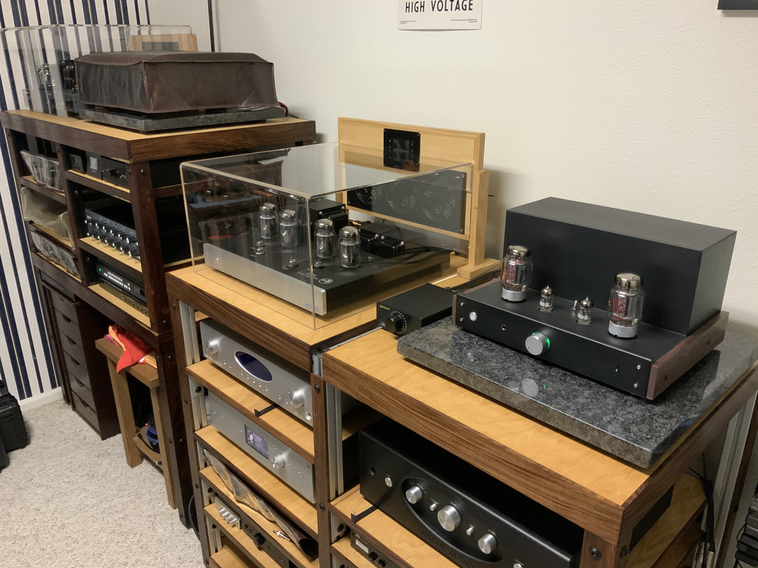
With the Klipsch Heresy I System
So, now that I have set up my living room system, I set out to do more testing on it. For those not familiar with my Heresy system, please first read the Heresy link above. A brief re-cap of the system:
Turntable (stereo): Thorens TD-124 Mk I with Thomas Schick 12" arm and Goldbug Clement II MC Cartridge.
Turntable (mono): Technics SL-1200 Mk II with Denon DL-102 Mono Cartridge。
Phonoamp: Arcam rPhono (to Gotham GAC-2111 interconnect)
CD Player: Magnavox CDB 262 (to Gotham DGS-1 interconnect)
Amp: Elekit TU-8800 (Belden 9497 loudspeaker cable)
Speakers: Klipsch Heresy I (alnico)
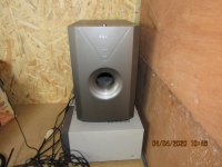
Subwoofer: Pioneer SW-8 (connected to amp with generic cable)
I started with the same Siemens 12AT7 and Russian KT88. It was immediately apparent that the sound was better than with the YL horns. It was already enjoyable but a little more sweetness in the massed strings, particularly when they really dig in (this is very challenging for systems), would not be amiss.
Pearl
12AT7 First, I swapped in a pair of old-stock GE D-getter 12AT7, and the sound immediately and considerably sweetened. The massed strings now only had a trace of the metallic about them. The soundstage moved back quite a bit. Yes, I lost a little resolution but I got more music. This confirmed much of what I believe of Siemens tubes - many of them are forward and lean (almost transistor-like sometimes) and are best used in vintage systems that are overly warm (usually not in spec).
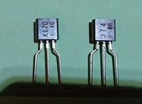
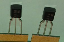
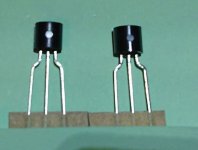
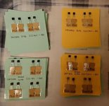
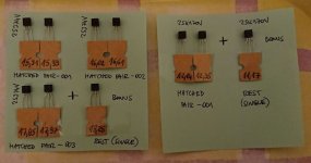
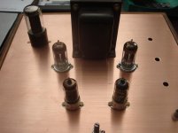
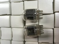
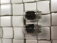
Output Tube Rolling It is not often that I have the time to do much tube rolling. I usually do the minimal necessary to get the sound I want. With more time on hand at the moment, I decided to do this review justice. I randomly pulled out a few types (all old stock; see pic at bottom) to test. I tested them in no particular order, and as I went along, I pulled out more and more tubes. So this is a lengthy read. I shall also talk more about these tubes after I finish the review proper, to make it yet lengthier. You have been warned.
6V6GT Then, I dropped in a pair of RCA smoked glass 6V6GT (lowering the output to around 2 watts; remember to switch the Power Mode to Low) and the sound further improved. Now, I could play anything. It doesn't have the grunt of the KT88 but the power is enough for me even in this large room for Arethra Franklin's I never loved a man the way I loved you and Janis Joplin's Pearl. No pounding bass but the full impact of the music comes across loud and clear. Those 4 live bonus tracks (1970 Canadian Festival Express Tour) in the Joplin CD are even better than the album proper; the immediacy is life-affirming! Similarly, Celibidache's 1969 performance of Bruckner's 4th with the Swedish RSO (DG) is coherent and compelling. Now, all these albums mentioned, though reasonably well recorded, do not belong to the top tier in audio quality, but musically they are compelling. Triode/UL I tried both again and found the difference in sound quality as well as nominal power much less than expected (probably more apparent with higher powered tubes) and so left the amp in Ultralinear Mode. vs LTA MicroZOTL The Elekit with 6V6 is roughly in the same power envelope as the LTA. But, as expected, the LTA has a more naturally fast transient and reveal more rhythmic felicities and subtleties.
6550 I next dug out a pair of old-stock 3-getter Tung-Sol 6550 (this is a very fine tube, best of the 6550's) and installed them. By now I was listening to Rudolf Serkin playing Mozart Piano Concertos (with Abbado; DG). A repeat showed the sound to be further improved. The soundstage is larger and there is more detail compared to the 6V6GT. It is still quite smooth. Then I found out I had not changed the Power Mode before the swap (still in Low Power Mode). I turned off the power, changed to High Power Mode and turned it back on. Even more air and definition. I replayed the Janis Joplin CD. Surely it sounds more punchy, more controlled, and the vocals and instruments become clearer. An unqualified success. It got so good that I played Hugh Masekela's Hope and played a few track with relish. The attack and presence of the Heresy is highly gratifying (the non verbal expletives highly stirring), and the percussion and bass are very decent. The audiophile's favorite stimela plays with momentum, virility and satisfactory slam. Of course, again, with the 8" subwoofer, when it comes to bass it is not as good as my YL's 15" woofer, but it is satisfying enough and tightly argued. I'd not think of playing this track with 2 watts (6V6) for enjoyment (testing is a different matter). But it is not all about impact; the system brings out all the atmosphere in Nick Cave's The Boatman's Call. In this outstanding album, the mournful, the confessional and the spiritual create a groove of their own, as powerful as any uptempo material. Sparse but beautifully shaded instrumental effects punctuate the landscape established by the moody keyboard and Cave's voice (one thing I like about him is his clear vocals; you don't have to read the lyrics). Yes, horns let you feel the mood better than conventional transducers. So far so good.
Nick cave and the bad seeds-the boatman's call.jpgPower Mode I want to take the time here to emphasize the importance of checking this when one changes Power Tubes. The amps has 3 positions: LOW (6V6, 6F6); MID (6L6 family, 7591, EL34) and HIGH (KT66, KT77, KT88, 6550, KT 120/150). When I changed to the 6550 (above) I by mistake (using the 6V6 setting previously) started with the LOW, which gave it a softer sound because of the lower B+. That was OK. BUT, if I now want to swap back to the 6V6 and forgot to set it back to LOW, I would likely run into trouble as now I'd be running the 6V6 at too high a B+, even if I am sure Elekit runs the amp conservatively. Keep in mind you can safely run a power tube at a lower B+ (with a change in sound, as per my experience) for fun and experiment, but not the other way. I am not sure whether I can do this on the fly, so I didn't try. So, always check.
5881 This is a rugged 6L6WGB type that can withstand higher voltage (as per instruction, I used the Mid Position). The pair are Tung-Sol's, even if one is marked RCA. Here I got my first disappointment. It has neither the sheer brilliance and output of the Tung-Sol 6550 nor the musicality of the RCA 6V6.
EL34 Keeping the Mid Setting, I swapped in a pair of Mullard xf2 EL34 (labelled HP). The sound is very good. It sounds detailed and powerful, enough to almost rival the Tung-Sol 6550, yet is musical enough to rival the RCA 6V6G. In fact, it made the 6V6GT sound just a little veiled. It is also a little smoother than the Tung-Sol 6550, which likely means different things to different people. To the average vintage lover who crave tube warmth (usually overly so) that is great; but to someone like me the leading edge is just a little too rounded, making the sound, sweet as it is, not as life-like, and isn't that the primary goal of horn users? But one can see why this tube is popular in SE amp configuration. My first SE amp was the first generation Audion Sterling over 20 years ago, and it was a good sounding amp. Later I got into Direct-Heated Triodes, and one of my 300B amps was again the (first gen) Audion Silver Night. There is no doubt in my mind about which Audion amp is better.
6V6G Given the findings above I set my sight on testing more 6V6 types. I wasn't thinking of 6L6G but I chanced upon a pair of Zenith 6V6G and used them (Low Setting). An utter surprise! It gave a mesmerizing, flesh-and-blood performance! It is not the surprisingly detailed sound that is so impressive. Images are larger and more palpable. In the Nick Cave album, the second half is a little less somnolent than the first, and there are more instrumental flourishes, which I dig (including a violin). In Idiot Prayer, Nick Cave's voice acquires more gravitas and urgency, and the various instrumental flashes have the truest timber (nowhere is this more apparent than the pizzicati). The most impressive thing is, good as some of the other tubes are, this sets down the mood more effortlessly. You don't have to get it; it gets to you. Downside? Yes, for the first time I hear some clipping in loud passages. This is known, the G has lower power rating than the GT. But for simpler music (I count this Nick Cave album among them) it is hard to best.
6L6G Inspired by the 6V6G and, given the uninspiring performance of the related 5881, I swapped in a pair of RCA smoked glass 6L6G. Mind you, the 6L6G sounds magical in my WE 124B amp, albeit in push-pull. As expected, the sound is very good and has much of the same qualities of the 6V6G. But there are differences: it is slightly less detailed; the images are a little less fleshy and the instrumental timbers a little sweeter (not to the extent of EL34). While in terms of presence it is edged out by the 6V6G, it has the advantage of more power (doesn't clip). A very fine effort.
6V6GT/VT-107A I continued my 6V6 testing by swapping in an older pair of 6V6GT that is also marked with the military designation VT-107A (the RCA logo is also larger). In my experience, early VT- designated tubes are usually superior, and it so proved. Compared to the first pair of 6V6GT I used, it upped the game considerably. This older GT tube has a little more detail and even better presence, dynamics and flow. Like the other pair of 6V6GT, images are smaller and it is less dramatic than the 6V6G. It has the advantage of greater power and is quite effortless with most material. Overall performance is excellent.
KT66 The sound of the (old-stock) GEC KT66 proved yo be as fat as its profile. It is a rich sounding tube, even smoother than the EL34, but its transient edge is even slower. It is obvious the Nick Cave album moves at a more deliberate pace. Of course, presence is not its strong suit. When I replaced it with the VT-107A I was immediately revived by more air and pace.
KT88 Now, although this amp has 3 power modes and allows you to use all kinds of tubes, I suspect it was voiced with KT88, as it is the only tube marked in bold on the Power Mode sticker label. So I was curious about the old-stock GEC KT88., made by the UK to counter the high-powered US 6550. The US never made this tube, and in my experience all latter-day and current productions don't hold a candle to it (as evidenced here by the Russian "Genalex"). Sure enough, this excellent (and very expensive) tube performed wonderfully, very much in the vein of the 6550, though a little warmer and also a little less excitable. With all the power available (like the 6550, the chassis is notably warmer than when the 2 lower power modes are used), Chabrier's Espana (Ansermet, London) was well controlled yet crackled with excitement. With plentiful air, this tube effortlessly separated the various strands in the back-up to Cave's vocals, and the violin and pizzacati are truthful. Compared to its British cousins EL34 and KT66, it does less beautifying, and has better air, leading edge and transients. Although it is still not as neutral and doesn't convey the mood as well as the best of the 6V6/6L6 family, it is still highly musical and has more power to boot. Wonderful!
Back to 6L6G To check on myself, after the very good performance of the KT88, I re-installed the 6L6G and, sure enough, I stand by my words. Whether it is the vocals or timbers of the various instruments (like the burst of the Hammond or the wail of the violin), this tube is still more truthful than the KT88. And the music moves along even more. And, yes, the mood. I firmly know, for me, since I can get away with it, I'll stick with 6L6G, 6V6G and VT107A.
Back to VT-107A At the end of tube rolling, I re-installed the VT-107A, and the impression is the same. This is the tube I am going to use day-to-day.
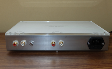
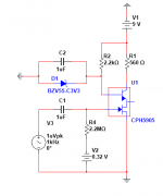
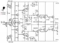
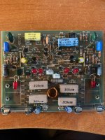
Enter the TU-8300 (pics at bottom of article) At this point I swapped in my TU-8300 (see Part I). Design vs TU-8800 The two amps have a lot of similarity. The first half of the 12AT7 is capacitor coupled to the second half, which then is capacitor coupled to and drives the output tube. Both amps employ feedback from the 8 ohm output tap. Both amps have protection circuits. The biggest difference is that the TU-8300 is Triode only (for 300B as well as medium to high powered beam and pentode tubes, such as 6L6GC, EL34, 6550, KT88, though sadly not 6V6) whereas the TU-8800 is switchable between Triode and Ultralinear and can also use low powered tubes like 6V6 (but no 300B). Of course, due to the ultralinear feature, the output transformers of the TU-8800 require extra taps and are more expensive to make. It should be noted both amps belong to Elekit's top offerings. The older 8300 does not even have an earphone output, and has only one input (a nuisance). The 8800 is much better ergonomically, has 2 RCA inputs (one wired parallel to a minijack input) and does have an earphone output connected to the transformer output. Unlike the desktop-driven design of TU-8150 (here), for someone like me who use only the RCA inputs, these extra's do not interfere with the signal path. 8300 Mods As mentioned in Part I, I did some modifications to the TU-8300 (pic at bottom). I replaced the input RCA sockets, hardwired the input with Belden 8451, changed the potentiometer to an older generic type (unlike others, I regard older designs as better, and they are really cheap) and hardwired it to the circuit board with the conductors inside the same Belden 8451. I also changed the two coupling caps on each side to Russian military PIO. Earlier, in an attempt to lower the input sensitivity, I had wired resistors to the input but I later took them out as it was not very effective. The resultant sound is a little warmer than the original. Used as Integrated Amp As discussed at the start of the article, due to high input sensitivity, both amps are better used as integrated amps. For the purpose of this article I did that for both amps. For the 8300 I had to change cables when I switched sources. I had actually never previously used the 8300 as an integrated amp. Used this way, it is actually much quieter than I thought. 300B I started with the Shuguang 300B. Initially, I was taken by surprise. Using the same albums, the vocal and instrumental placements in the soundstage were noticeably different than before, the color was darker, the bass was muddy and things fell apart with orchestral tutti. I was not happy and after some thought swapped out the Mullard 12 AT7's and swapped in the GE's I had been using in the 8800. Good Lord! Now the 8300 with the 300B sounds almost identical to the 8800! A lot of people go for Mullard, but not me. Aside from a few specific types, it has its own colored, usually fat and veiled sound. The GE sounds much more neutral and correct. Thus tubed, the 300B turned in an equivalent performance to the best of the beam/pentode tubes. I expected this, as imho the 300B is one of the few successful modern tube production stories (of course NOS true WE300B is better, but that's untouchable). Russian KT88 Satisfied, and as I was not going to do all that tube rolling again, I just tested what I started with, the Russian "Genalex", and the result was pretty good, much as it performed in the 8800. Pointers vs. 8800 Keep in mind the 8300 had been modified to yield a warmer sound, so it is right to conclude the 8800 is a little warmer than the stock 8300. Even more obvious, although the 8300 is quite quiet, the TU-8800 is dead-quiet. With some of the tubes, there is no noise whatsoever; with some others, there may be a little noise, but I am confident it is tube noise/rush. Keep in mind with 97 db loudspeakers tube noise is an issue.
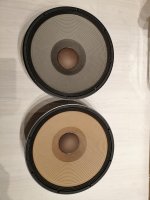
The Lundahl Transformers!
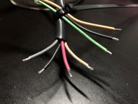
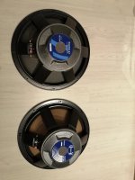
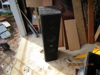
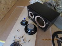
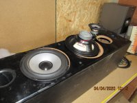
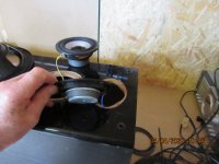
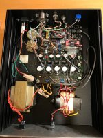
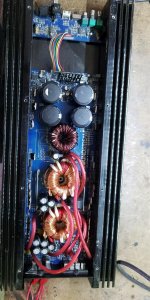
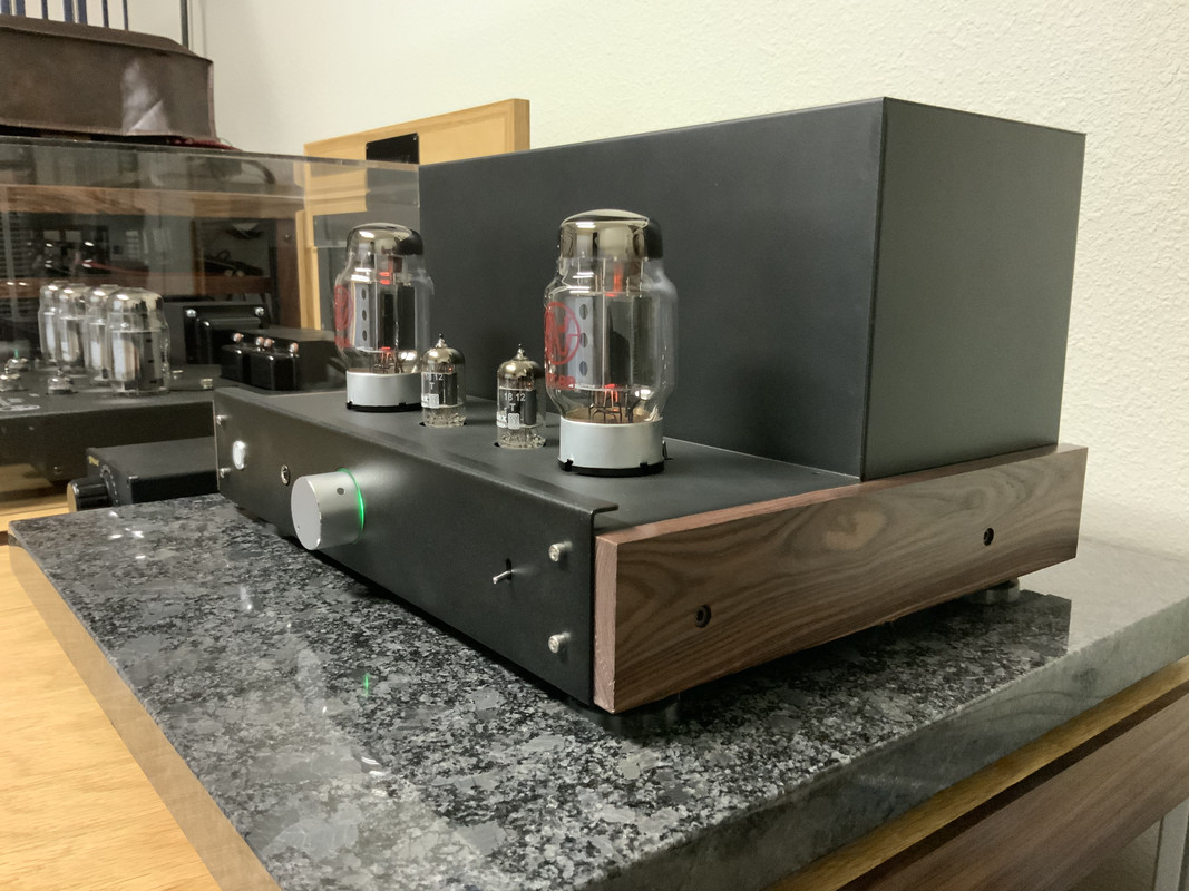
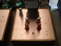
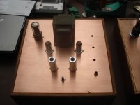
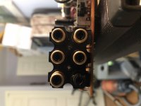
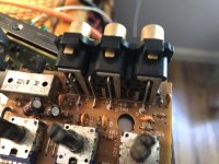
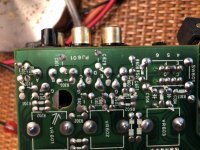
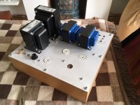
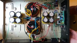
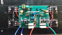
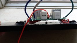
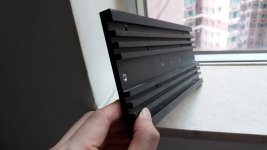
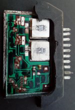
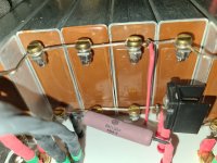
And, now gentlemen...the high point of this review. It is not every day that one gets to compare transformers! VK of vkmusic is a perfectionist who for the longest time has been offering upgrades for many of the Elekit kits he sells. These were usually capacitor and resistor upgrades (some of the resistors had to be custom made). Since the acclaimed TU-8600 300B amp, VK Music has gone further, offering upgraded transformers in cooperation with Lundahl. It is an arduous and time consuming task. VK informed me that the final version has three previous prototypes. In the top pic you can see they are even beefier and heavier than the stock ones. Installation This proved to be a bit challenging. It was not difficult to remove the stock transformers and wires, but the metal bracket they are mounted on was a problem. This is because there was not enough clearance on the right side of the chassis to allow lifting of the bracket. And because the screws of the Lundahl transformers have to be mounted from the bottom (see pic). I did not want to do the unsoldering needed to remove the circuit board. What I did was to stand the chassis on its right side. This way the bracket can be tilted 45 degrees from the chassis, allowing tight room to work (especially with the right output trans). I first got the screws in with my hand holding just the bit, then use a 90 degree screwdriver for the final tightening. The obvious message is it is much easier to have the upgraded trannies when one starts to build the kit! If not, one can upgrade with a little more effort.
Cover shows a close up of Cash's face, looking at the camera.TU-8800VK--Sonic Impressions I continued to use the GE 12AT7, the Low Power Mode and VT-107A. Brand new transformers take quite a while to run-in, but I'll cut to the chase: Now I am at around 30 hours; even without much run-in, the Lundahl Transformers are a significant Upgrade! From the first note of the Nick Cave album I noticed the difference. I replayed every album and also a few new ones. How one transformer is better than another is sometimes a subtle (but very important) thing that is hard to describe, harder than say the difference in sound between resistors or caps. Changing the transformer changes everything and it is hard to separate the impovement into components, but I shall say a few words on the sonic merits:
Ease of Flow Elekit, especially the 8800 (and the 8300), has a neutral and resolving sound. With the right tubes, as described in the tube rolling section, the flow can be impressive, but with the Lundahl's, it is significantly enhanced. This is as true for Nick Cave as for classical music. Paray's Dvorak 9th (Mercury CD) was as exciting as ever, yet totally non-grating. To me, better ease of flow is at least partly due to better microdynamics. As in real life, ease is a precious thing; unlike in real life in this case you can for sure buy it with money.
Enhanced Bandwidth This is immediately obvious and the most objective parameter. There is more air in the treble and a cleaner, more tactile, yet punchier, bass. It changes Nick Cave's vocals and the piano tone, now even clearer (sometimes even ethereal) and more resolving. All the instruments have more sheen. In classical music, it is obvious the soundstage is also significantly deeper and airier.
Sweet Presence Generally speaking, presence, or the feeling of a live performance, requires a fast transient attack (and horns) and can come at the expense of a little sweetness. Not so here. The Lundahl, even with increased bandwidth, makes everything sweeter, yet presence is enhanced. Johnny Cash At Folsom Prison (Legacy) is an excellent live recording. Here, the audience is perfectly captured, Cash's voice smoky, the guitars sweet and beautifully delineated. In Jackson, a duet, June Carter is just dynamite!
More Forgiving of Tubes As you have read from the Tube Rolling section, I roll tubes a bit to find out what I like (usually a neutral sound, but it has to convey presence and mood). Given the increased ease in sound, I suddenly had the idea to give some of the tubes I did not quite like before another shot. I rolled in the Russian "Genalex" KT88 and, surely, the performance is significantly better than before, less etched when the going gets rough. Keeping the output tube the same, I then tried out the 12AT7's which are so critical to the sound. The Siemens 12AT7 is still a little forward but it is now quite acceptable. The Mullard 12AT7 is still a little too dark and veiled for my taste, but it also performed very well. So, "rolling" transformers is even more effective than rolling tubes, when done right.
TU-8800VK--Earphone Tests I use earphones only on occasion, so this is brief. I first connected my Beyerdynamic DT880 (97 db, 600 ohms) and listened with satisfaction to Otto Klemperer conducting the Philharmonia in Dvorak's 9th (Angel, LP). But when I played the Nick Cave CD I realized the proceedings were a little heavy and the bass not well resolved. I was sure that is an impedance question, and so switched to the lower impedance AKG K701 (105 db, 62 ohms). Sure enough, that immediately cleaned up the sound and improved the flow, and now it resembled the sound via the loudspeakers. I see there are internal 6-position dip switches that select resistors, surely for impedance and level matching, but lacking the manual and not willing to open the chassis again I will leave it at that.
Comments on TU-8800(VK)
Stock Version As I'd expect from Elekit, the TU-8800 is a very capable amp. A decade on from the TU-8300, the TU-8800 is a lot more versatile and ergonomically desirable. As I'd also expect from Elekit, it is a very neutral amp that reveals every change in tubes and components. Even with current production tubes, it turns in a very good performance. Highly Recommended.
Lundahl (VK) Version The million dollar question is, at a premium of roughly half the cost of the stock amp, is the transformer upgrade worth it? Experienced tube users, especially vintage aficionados, know just how important, and how costly, good transformers are. Personally, I am very impressed by these Lundahl transformers. They confer abundantly that most precious Final Touch, and that elevates a very good product to an outstanding one. A lot of DIY people spend a lot of money upgrading caps and resistors but, I tell you, as reported just above, changing the transformer is even more transformative! Old stock tubes are expensive and, unless one already has a stash (like I), to me it pays to start with the better transformers. Enthusiastically Recommended. In fact, it had me thinking about upgrading the transformers of my TU-8300 (this Lundahl is not suitable). Also, if I don't already have the TU-8300 and the 6V6 based TU-8150, I'd buy the TU-8800VK without hesitation. It is also time for me to do some surgery on the TU-8150 (bypassing the earphone and mini-jack input that I don't use) to bring its performance closer to the 6V6 in TU-8800 (though unfortunately there is no transformer upgrade).
Tube Rolling Given the versatility of the amp, tube rolling is a temptation most cannot resist. Yet I'd like to give some guidelines here. In general, I think, even with the most humble of tubes (the current stuff) one can get a good sound. Get your system right before you go crazy rolling tubes! There are priorities. No amount of tube rolling is going to save a system that is intrinsically unbalanced. But, when you get your system to sound right, tube rolling becomes the coveted final touch. In this article, because of my stash, I can indulge in some of the best, but this is just for reference as to how far one can take the amp to. Here, I'd like to remind you upgrading to the Lundahl transformers is more essential than spending a large sum of money rolling tubes.
12AT7 This is very critical, and your system and taste shall likely come into play. Experienced tube users know that the input/driver tube(s) have as much, if not more, effect as the power tubes. Unlike the many tube "gurus" out there I usually shy away from a recommendation, because I believe there is no best tube (aside from old-stock tubes are better than current ones), and context (a system approach) is just as important. That said, I do believe the old-stock GE D-getter 12AT7 (not that rare) is a very fine mate with this amp. A new pair is not that expensive and used and test good tubes much cheaper on Ebay.
High Power Output Tubes With higher B+, more inefficient loudspeakers can be driven adequately, as evidenced in my Part I Report with the 87 db LS 3/5A. But, even with my 97 db Heresy's, the higher power mode still performed admirably. Basically, I think the designer designed it using the KT88 as prototype. Even the Russian "Genalex" KT88 sounds pretty good (especially with the Lundahl's), and I'd wager the KT120/150 would too. I'd avoid the KT66. And the performance of the genuine old-stock GEC KT88 propelled the amp into another league altogether. But the genuine item is very expensive and off-putting to most people. The old-stock Tung-Sol 6550 is almost as good, but cheaper. Enough said.
Medium Power Output Tubes I'd think EL34 is worthwhile. If you already have a stash of EL34 or 6L6GC/WGB etc you would have some fun. I certainly have not tested the vast 6L6 family extensively, but for now I can recommend only 6L6G.
Low Power Output Tubes If your system allows the use of low powered tubes, greater power to you! For me, I just love the flea-powered 6V6. Old-stock 6V6's are very reasonably priced, but I know not many can use this kind of flea-power. But, if your loudspeakers are efficient, and your room is small, try it for not that much money! You will be surprised! For me, a horn user, it is my preference.
Power Mode Switch I'd like to implore you once again that it is imperative for you to check the position of the switch when you change power tubes.
Integrated Amp vs. Power Amp If you want to connect more than 2 sources and if you have to use a preamp, make sure it is one without gain (passive, TVC, or even Elekit's own TU-8500 in Unity Gain mode).
There! It took forever to write this article on a Windows XP!
Top, L to R: 6V6GT, VT107A, 5881, 6V6G, 6L6G;
Bottom: L to R: EL34, 6550, KT66, KT88

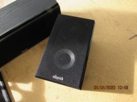
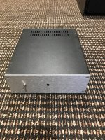
Elekit TU-8300 in action
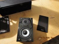
Innards of the TU-8300


 .
.