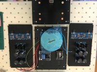
Because I have a lot of free time these days, I started testing few multi-way speakers I have here, sitting around, unfinished.
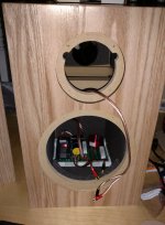
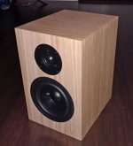
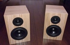
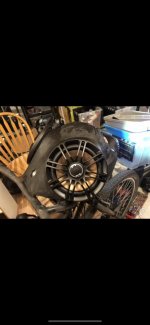
One in particular came to my attention: a project of 2-way using some nice pro audio 15'' woofer that happens to climb as high as 4khz while having some very manageable specs to go down to the first octave.
Nothing to win the gold medal of Hi-Fi Olympics, mind you. Just a project for fun, to pass time while I'm isolated at my place.
🙄
So, that particular project reminded me of something very important. Maybe one of the oldest problems in audiophilia, especially for us DIYers.
How, supposedly, the box is the least worst of the solutions
We all know there is basically 3 types of boxes:
- Ported
- Sealed
- Passive radiator
The sealed one is the simplest, obviously. The ported one is the efficient one, while the PR is the ''technological evolution'' of the ported one, so to speak.
So far, nothing too complicated to understand. That's the ''box world'' even though many exotic configurations exists which are essentially variations on the theme.
But here comes the Open Baffle. And, just to be very clear, that's not a thread about how magical are OB's... They're not.
On one side you want to avoid the acoustic short circuit of an open baffle, a ''naked driver'' that most of low-frequencies abilities are stripped off, but on the other hand you ''bury'' the problem in a box... and that generates other problems. Problems ''solved'' mostly by stuffing absorbent materials into said box.
Compromises. Compromises everywhere. Insert a popular meme here.
Problem is, there is a general misconception about an idea in which the box itself -if poorly built- will generate resonances, noises and bottomline what can be called distortion, from the source (music) to our ears.
In fact, the vast majority of boxes, even built by beginners, are probably built in a way that they cannot generate resonances that will be audible, especially not at low/moderate SPL.
What's left then? LEAKS.
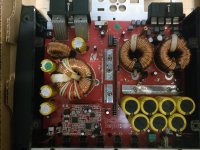
Ports, obviously, but also the driver itself. The 15 inches pro audio driver I was talking about earlier. Event though I use it in a sealed box, the internal resonance builds up and it leaks badly through the (big) cone. Of course, I can stuff stuff inside. But it's not enough. Unless I'm looking for other acoustical problems somewhere down the road...
Which do you think, of 25mm thick plywood V.S. 0.5mm paper will block the most sound energy? The plywood, obviously. The big cone here is a massive leak. Only the highest frequencies are blocked.
And, bottomline, it's distortion. Sometimes not too uncomfortable, but distortion nonetheless. The resonance build-up of the box which leaks through the membrane is audible enough to pollute the final sound rendering, sometimes in a very bad way. Like it's the case with my huge 15 PA driver.
The resonances are sound energy that bounces internally, trapped, on the (very) rigid enclosure's walls, and that generates reverberation (echoes) until that energy dies or leak somehow.
Almost impossible to correct on EQ. You can correct amplitude and frequency on a EQ but not reverberation time (RT), unless you try to dim the frequencie(s) where the resonance build-up is at the worst, but then you cheat on the signal, which is not good. Better to solve the problem at the source. Instead of putting out a fire, it is better to avoid having one from the start ...
These resonances are well-known with the ported boxes. That's another leak, ports. The resonances build-up leaks through the port(s) and even though there is many designs to avoid partially the unwanted effects, it's still a leak. At the perceptive level, the ''ported box reputation'' is that the bass is ''slow'', which is mostly explained by the reverberations, of the higher frequencies, that are building up and then leaked through the port, which cause a ''blurr'' in the perception. Less ''clean'', also a common way to describe it. And that is exactly what is it: less clean because polluted by distortion: unwanted sound energy on the original path from the source.
The human ear is unprecise regarding amplitude and frequencies, but very precise in the time domain. We can detect very small RT and that affect our perception a lot.
So here it is: I wonder if a fellow DIY enthusiast or any lab or company ever did a study, a test about the following:
To enclose a small full range speaker IN a larger box.
First, a completely closed box, sealed like a can. Then measure what comes out using sweeps or pink noise.
The result will be the resonance of the box itself, its walls and possible sound energy leaks, within limits of what the small fullrange can generate, in both frequencies and SPL.
Then, the same process but with a box, still of the sealed type, loaded with an inactive (bigger) driver. Ideally with a burnt/locked voice coil so it won't generate sound waves by itself...
The idea of course would be to measure what comes out via the membrane. So we can have a good idea of the leak compared with that the benchmark (the walls of the box, from the first test).
Any idea? Any comments?
🙂

 to Patrick (@EUVL), @Morde, and a fantastic DIY community