I am starting this thread because the iraud200 thread started to become too long to read and process because of all of the little experiments, discussions, etc. This thread is only for quick reference on how to manage the iraud200 board. Use the other thread for more info. on fine details and more detailed understanding.
I chose the iraud200 boards from an ebay seller because I wanted a 2 ohm capable single channel board capable of handling around +/- 70 volt power supply and 600+ watts per channel. iraud200 seemed to be the only option available for these specs. The next closest runner-ups were the iraud350 which at best handles a 4 ohm load. The iraud200 and the iraud350 are close cousins. That means that they share some attributes and problems.
Both boards have the fundamental problem that they are way over-driving the irs2092 chip. One of my copies of the iraud350 worked, but eventually it was the irs2092 chip that failed. That board had a small, tall heat sink pasted to the irs2092 chip to help with the problem. I over-currented the transistors and lost them and replaced them with irfb4227 for more current, which the chip was apparently unable to drive despite heat sink because the 2092 was the next thing to go. I thought it might work to try a board that carried the irfb4227 stock, so I went for the iraud200 and hoped for success with 2 ohm loads. I was sorely disappointed up front. I really wanted this to work, so I became determined and eventually I successfully forced the board to behave. I would like to share the secrets of this success with other DIYers who see the iraud200 as a potential option to get what they want.
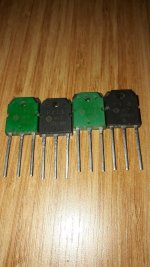
The iraud200 sports excellent protections and current/power capability. The irfb4227 transistors are magnificent and capable of stunning currents such that just two of them can be used to drive over 20 amps through a 2 ohm load.
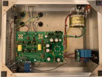
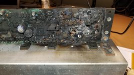
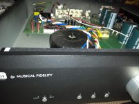
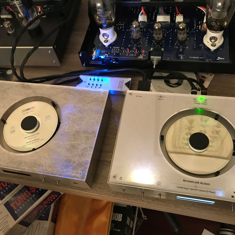
When my board(s) arrived, I was greeted with obvious Quality assurance failures that made me very suspicious. No heat sink grease on the transistors .. no heat sink on the irs2092 chip. I did not dare power them up until I had the transistors greased and a tall little heat sink on the irs2092 chip. When the parts arrived for that, I was in for yet more disappointment. The boards fired up and worked beautifully for about 3 minutes. Then they quit. I thought they were burned, but actually not .. the boards sport overtemp protection which had turned the boards off because the heat sink had become too hot (imagine what would have happened with no heat sink grease).
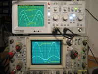
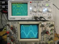
Later, It turned out that the cause of the overtemp failure was a high frequency parasite that resonated in the output filter and leaked back into the feedback loop. Before I knew that though, I learned a lot of things about the board in my attempts to beat this problem. To make the list complete though, I am going to list all of the problem of the board including those already mentioned.
1. No heat sink grease on the transistors (easy fix with heat sink grease)
2. No heat sink on the irs2092 chip which can't drive irfb4227 safely without it. Get a small heat sink from ebay or such about 10mm by 10 mm by 35mm and get heat sink glue to glue it on there .. try not to get the glue on the pins of the chip (don't know how crucial this is .. never became a problem for me)
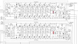
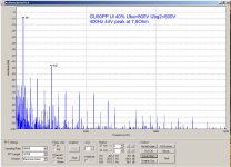
3. The fudgers did not follow the proper feedback loop specs from the example docs. Don't know why, but they made several changes. First, they eliminated the 150 pf delay cap and accompanying 1k resistor (really bad idea) out of the feedback loop. Second, they slightly adjusted the ohmage of the floating ground (no biggie) third, they eliminated the input capacitor and allowed you to direct DC drive this board .. it should in fact be able to output DC current (interesting, may find uses for this later) . You can forget about the DC input/output option they built in pretty much and not worry about the tweaked floating ground except that I think it adds a little hum to the output. The killer is the elimination of the delay cap and resistor in the feedback loop. This exacerbates the problems we already have, trying to drive the high gate charge of the irfb4227 by boosting the feedback switching frequency to around 800khz. It also feeds the parasite OUCH!!!! This thing is trying its hardest to burn out the irs2092. Turns out that the iraud350 does the same thing. If you have either board, you will want to fix the feedback loop.
To fix the feedback loop, order 150pf ceramic caps rated at at least 150 volts and 1k surface mount resistors of the proper size. This board has a single 200kohm resistor that acts as the feedback voltage reducer. You can continue to use it, only you have to put a 1k resistor between it and the transistors output, then connect the junction between those two resistors to ground through the 150 pf capacitor. This slows down the switching frequency and in my case allowed the board to run without overtemping. However, it was still very hot and it made me nervous to run it/them.
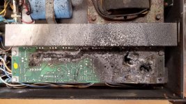
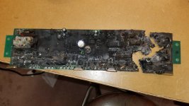
4. Interestingly the high temperature would sometimes disappear for as much as several days, which I eventually learned to be a result of a faulty connection between the output filter capacitor (the big one just behind the heat sink) and ground.. or .. eventually ... a destroyed output filter capacitor. When the connection from cap to ground would disappear, the parasitic resonance between cap and output inductor would die with it, the board would cool off, but obviously, there would be a lot of rf on the output line because only half of the filter would be operating.
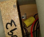
5. The output filter capacitor was not rated properly. It should have been 0.47 uf and 200 volts or higher AC rated film capacitor. In stead, it was 1 uf and 100 volt, which the parasitic resonance destroyed after a period of time, leaving a board that didn't overheat, but also basically had no proper output filter capacitor. You will need a high power soldering iron .. like 40 to 60 watt to swap that capacitor out .. otherwise the solder won't melt well enough. .. but don't reach straight for the correct 0.47uf 200 plus volt capacitor to replace this with because it's a potential parasite feeder .. see number 6.
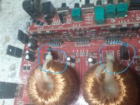
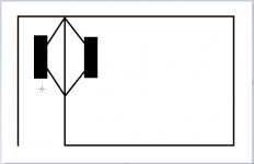
6. After putting the correct capacitor in place, the board(s) still ran dangerously hot. I added some resonance dampening caps and a resistor (I'll show these crucial details in detail) .. this got one of the boards to behave, but the second one didn't because its parasite was a little livelier. I tried tweaking multiple resistors in the feedback loop to change this to no avail. That's how I became convinced that the parasite was living in the output filter. Smaller output filter capacitance in the output filter helped cool the board, so I ordered several options of parts to take that output filter cap position. Eventually, the combination that killed the tougher parasite on the second board was a 0.27 uf film cap rated at 275 volts as the output filter cap, and a second capacitor of 0.22 uf (275 vac film) connected in series with 4.1 ohm 4 watt (suggest at least 5 watts for this 5 ohm is probably fine) dampener resistor across the boards two output terminals. (output and 0 volt .. right next to each other) Whala ... success!!!!!!!!!!!! The parasite could not make it past the tipping point, so it remained a virtual nothing of empty space-time.
7 The board has 3 10uf (nonpolar) ceramic caps that help the floating power supply function. These were smaller than the caps on other variants of the circuit I had seen, so I purchased a bunch of 10uf 50 volt and soldered them on in parallel with the pre-existing caps. This is the first parts change I did to try and fix the boards, which didn't work, so I don't know if it's required or not, but it's a good idea I think.
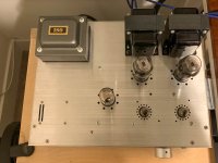
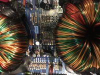
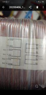
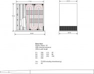
8 There are two versions of this board .. the 4 ohm version and the 2 ohm version. The 4 ohm version has a smaller output inductor. Yes, I know, there are four pins on the inductors which makes them look like pairs of inductors, but two of those pins are not electrically connected and only stabilize the inductor. If you want the 2 ohm version, make sure it says 2 ohms and maybe double check that the inductor is filling up its (square) space all the way ..
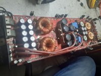
9 also, don't get a version of this board with oversized storage capacitors because they'll get in the way of a heat sink for the output inductor. The output inductors are a little small, so to stay safe, heat sink grease a heat sink to them and then when you are done fiddling, replace the heat sink grease with heat sink glue. The output inductors definitely have to have the heat sink to protect them if the boards parasite problem has not been fixed yet. The main heat sinks are likely to require supplementation as well, especially if you haven't killed the parasite yet.
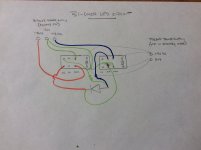
10 Using ferrite beads on the 0 volt lines to the power supply, I was able to get two of these boards to co-exist on a system with two plus poles and two minus poles that shared a common 0 volt line. This normally risks the 2092 chips getting all befuddled with rf on the 0 volt line that comes from the other board, but I was able to smile by simply putting two ferrite beads on each 0 volt line. Yay!!!!!!!!
So, this is the intro. page .. as days progress, I'll get to work making all of this information more visual and understandable.


