Does tube temperature equate to current?

After giving up on using my amp with 300B, I put the 6B4G back in and I noticed one side was somewhat weaker than the other. I figured it was one of the tubes not properly seated in the socket, usually it's the Russian driver tube because the pins are slightly narrower. I did my usual wiggling and it settled in place, then went out again. I went to wiggle the power tubes after and I noticed that one tube was much cooler than the rest. I used my new handy dandy IR thermometer that I've been using on everything, and are being used to take peoples' temps too in the age of Covid-19, and sure enough one tube measured 150F or so internally where its mate measured 250F. I checked the other pair and it was more like 220/230, so a better match. I also swapped the cooler tube with the hot one to see if it was something other than the tube but the cool tube stayed cool. And cool is relative, I wouldn't want to grab either tube.

Does this mean that the one cool tube is drawing less current and generating less heat and hence the other gets more? I know this isn't a direct measurement, but can I make this assumption? And how would I measure individual current with a shared cathode? Can I just measure with a single tube and then swap?

What got me started on using the 300B was that I thought I was going to need a new pair soon after one of the filaments crapped out a month or two ago, and I wanted to try something other than the Sovtek 6B4G. I had a spare that I used but it likely didn't match. I may be in that situation anyway.

It sounds as good as ever at the moment, when the driver isn't seated it sounds distorted since one tube isn't getting voltage on the grid and it sits at ground.

Rpi4B-Volumio-Amanero-Acko Reclocker-TP BIII DAC - ISSUE

I have the following setup, Rpi4B-Volumio-Amanero-Acko Reclocker-TP BIII DAC and I cannot get the Amanero 384Combo USb input working to save my life. I have spent a lot of time trying the settings available in Voluimo and loading various versions of the 384Combo Firmware to no avail. Does anyone know how to get this to work?

I have managed to get my Windows PC to successfully stream DSD via Foobar,although it was a battle, I got good results using DSD-WASPI (Event).

If anyone can help it would be greatly appreciated.

AVO VCM163 glitch

Doing some "weeding" of my loose glassware and found a nice PX4 in a box. Tested perfectly for Gm and Ia on the VCM163 but when I switched from "Gm" to "gas", breaker flicked out and blue fault light lit up. Oh dear, too bad, never mind - time to bin it, but I was deeply suspicious as the PX4 showed no sign of blue glow when in the Gm test mode. Tried a new tactic - briefly turn the power off before doing the gas test. No grid current, no gas. no breaker : good tube. What could be wrong with my VCM163?
M

Help with a 120Hz buzz on an Aleph J

Hello everyone. I'm posting for two reasons. 1: trying to get some help with a minor issue on my Aleph J and 2: to hopefully learn something in the process.

I have built an F5 and Aleph J. Both amps have the exact same power supply parts, case and PS board from the diyaudiostore.com. The Aleph J has a 120Hz buzz in both channels when no inputs are hooked up. The F5 does not. Both amps work and sound great. Enough about the F5. Observations about the Aleph J:

1: The buzz is 120Hz measured by a frequency monitor and the very inexpensive scope I have. Approximately equal in both channels.

2: When a preamp is hooked up, the buzz quiets to the point you have to get very very very close to the speaker to hear it. This means normal listening volume you really are not affected by it.

3: Touching the shielded wires on the inputs increases the buzz.

4: Disconnecting the inputs from the PCB board has no effect on the buzz.

5: Shorting the inputs (hook + to -) eliminates the buzz.

6: Safety earth and the only connection to ground (through a cl60 thermister) from the power supply are to the same bolt to the chassis.

I'm assuming this situation is likely from a ground loop. Here is what I have tried to eliminate the buzz ( I realize some of this is not specific ground loop related):

1: Disconnecting input wires from PCB, checking for no continuity with the chassis on the inputs. Changed from a twisted solid pair to Cat 5. No effect.

2: Changing orientation of the transformer both by rotating and tipping up on its side. No effect.

3: Checking and rechecking continuity from the MOSFETs to the chassis. No continuity from any MOSFET to chassis when the power supply is disconnected.

4: Mains are run though the base mounting plate under the plate to the euro block shown in the picture. They are twisted the whole way. No effect.

5: Connecting the input grounds together has no effect.

What I find most curious about this is that the amp quiets when a preamp is connected. I'd like to understand this as much as fix the problem. The amp really does work very well and I know I'm letting my obsessive nature take over here. Any input or direction would be appreciated.

Attachments

  • amp.jpg
    amp.jpg
    713.9 KB · Views: 254
  • board1.jpg
    board1.jpg
    988.3 KB · Views: 234
  • board2.jpg
    board2.jpg
    784.1 KB · Views: 229
  • powers.jpg
    powers.jpg
    815.4 KB · Views: 241
  • torroid.jpg
    torroid.jpg
    984.3 KB · Views: 239

Rogue Atlas Output Transformer

I'm curious about the design of the secondary windings and wonder if heavier gauge wire is in the four ohm section, or if multiple windings are used.

Also, my hunch is that the Paradigm Studio Reference 100.2 may be better coupled using the 4 ohm tap. Mine play plenty loud (105dB +) with solid bass. IIRC, they dip below 4 ohms at a couple points.

Hope this post is in the right spot with two questions. Thanks for any help.

Found a Used PACE MP-1 (Tip doesn't get hot, suction works) Opinions?

So I found a Pace MP-1 desoldering station w/ SensaTemp SODR-X-Tractor Handle for $75 shipped to my door. I know that Pace is considered by many to be one of the best desoldering branded tools on the market and rarely do they show on Ebay in any type of working condition. I figured even if I can't get the desoldering station to heat up the tip, I can easily get my money back with just reselling that upgraded handle/iron. That is if the problem isn't in the iron itself (I really hope not), but based on the quote below, I believe the issue is in the desoldering station.

The seller stated: "Tested to power on. Suction appears to work. The tip did not get hot. The main station makes a rattling noise when turned over."

I should have it by the end of the week and I wanted to go ahead and reach out for any info someone could provide if they have worked on this unit before. From what I can gather, this unit has not had any attempts to repair it once it stopped heating up the tip. I assume this because of the quote above, if they know something is moving around inside the case, but don't what it is; that makes me assume it has never been opened/worked on.

Opinions are welcome, even if you have never held this unit in your hands. The theory of operation of a normal soldering station should hold for any desoldering station aside from the vacuum pump. I figure another option is to get an affordable desoldering station off Ebay (station only w/o pen/handle) and use the MP-1's iron. This may obviously require some adapters/modifications.

Attachments

  • Pace MP1 Pic 1.jpg
    Pace MP1 Pic 1.jpg
    129.8 KB · Views: 344

Amplifier layout vs sound

I have been modding a power amp, mostly PS improvements(caps) and signal path resistors.

I decided to argument the power supply lines (lots of shelter in place time). The original supply lines from the main rail caps to the driver/output transistors is a series connected line of parallel runs of 23 gauge wire. There is at least 4 junctions points in the power supply path making the rail feed to the first transistor. I removed those 23 gauge jumpers, replacing them with a larger size wire to transistors. Also, since the supply to the drivers were on the end of this series supply line, I wired a separate supply path to the drivers.

I then tested the amp and there was an nice improvement in detail and dynamics.

While looking over this supply path I discovered that the output layout had additional quirks. Each channel has a push and pull section. The layout was different on each channel. One side had the output transistors in a series chain connection path to the output point like the supply line. That path had the series connection through several single 23 gauge jumper(short) connections. The other channel had (push) 4 output transistors set connected to a single pad, then through a dual 23 gauge jumper. The other 4 transistor (pull) path was a combination series/ parallel paths. All these differences due to a single sided board design limiting connection paths. There are also additional wire jumpers from the diode bridges to main filter capacitors.

So with time and curiosity (limited money investment) I started a major mod effort. I first connected (each channel) all push and pull transistors to the output point in a parallel path connection through bigger solid copper wire. Each transistor had it's own output path.

The sound became very detailed, the increase in bass output easily noticable. The only problem is it lost it's music appeal, at least to me. The top hats shimmered, the bass solid, soundstage better defined. The casualty of this change was the midrange. The overall sound (of my system and to my taste) lost its musicality.

This was a mod step I didn't like overall, and I removed the parallel transistor connection, returned to the original series output connection path but retaining the larger wire( sans the 23 gauge). The musicality return.

I have modded/played with many digital CD/DVD circuits and have a good understanding about the importance of layout in those devices, but amps? That is, discounting size and type of materials, the connection/layout matter more than I thought..... Now that the shimmering top end, solid bass definition is compromised, I feel the loss. Can't I get both that and the musical mids from this amp? Any suggestions. I don't what to wear out the screw mounting holes taking this apart another 10 times.

OK magnet experts, here's a weird challenge for ya

I was given a set of kitchen mitts for Christmas
Amazon.com: HOMWE Extra Long Professional Silicone Oven Mitt, Oven Mitts with Quilted Liner, Heat Resistant Pot Holders, Flexible Oven Gloves, Red, 1 Pair: Kitchen & Dining
to replace some beloved old ones that had just worn out and didn't really work any more.

These long silicon mitts are much heavier and hanging them is a problem. The old ones I stuck key rings on and they thus stuck to some 1-1/4" magnets on the back of the refrigerator. The new ones drag the magnet down the refrigerator. I brought a magnet with a hook but same thing. There is not really an alternate spot to hang these
--> Need more powerful magnets!
But WHICH? I was thinking about raw flux and patterns thereof, and looking at SO many magnets on Amazon, sheesh. One says "adhesive backed" so thin double sided tape could help. Ideas?

Conversion of linear to log pot using resistor

So I tried this with my homemade amp a short while ago after getting some new 100k POTs that are linear type B ones since my original became quite scratchy and was cutting out from being a used part.
Put a 47k resistor from the middle POT pin to ground of it in my circuit and it performs surprisingly well.
Is it log? Hell if I know, but it does ride the volume up much more slowly until it reaches a point where ears and linear pots don't match and it ramps it up properly to my ears.

I made sure to first do a line load test and put a 47k resistor across the line inputs to my amp with volume at max and input set low and dumped the 47k across it and it didn't decrease volume level so there seems to be no issue with pull-down or impedance issues.

Curious how many of you have done this to convert linear volume potentiometers to pseudo log types and your experience.

For those lost to what I am talking about here is some essential reading in my opinion..
http://geofex.com/Article_Folders/potsecrets/potscret.htm

Toxic two-wheeled truck tires? Terrible!

I performed a web search on the topic of this thread but found no information that applied, and knowing not only the generous spirit of the members on this forum but also the fact that many are experienced in various technological professions and are all around "sciencey" kind of guys, I humbly post it here in the hope that someone can shed some light on a most perplexing mystery.

I own a small two-wheeled truck of tubular steel construction with a small open steel platform at its base which rests and rolls upon two pneumatic rubber tires. It is the kind of cart normally used for transporting heavy objects such as large boxes, furniture, and appliances over short distances. In my area it is commonly called a "two wheeler". As the spring season wore on and the weather warmed the lawn grass began to grow again and I began my springtime outdoor chores. One of those tasks involved moving some items over the lawn with my two wheeler and a few days after doing so I noticed that there were yellow tracks in the green grass where the tires had passed over. I took notice but had little concern because as the grass grew the yellow portions of the grass blades grew upward with green portions of the same blades pushing up from underneath. The yellow portions of the blades were at the top where the tires had contacted them.

To the best of my knowledge the tires have never come into contact with any herbicide or other poisonous substance and the truck, which is about two years old, has never been used off of my property. I purchased it at one of the large home improvement stores here in the US. It was manufactured in this country, but the pneumatic tires, which appear to be made of a curious amalgam of normal rubber and perhaps vinyl, are embossed with a phrase that indicates their place of origin is a geographically large Asian country with a tremendous population and a large manufacturing base.

Could the tires present toxic contact to plants? I can think of no other explanation. I am not overly concerned as the effect on the grass was temporary and superficial, not systemic, and the green grass is now growing in the affected tracks and seems to be perfectly healthy. I myself have no intention of eating the tires but I will be sure to wash after handling them for purpose of inflation.

If anyone has heard of this effect from another source or could offer an educated guess as to the cause of the yellowing of the grass in the tire tracks which cleared to green as the grass grew, I would be interested to hear from you.

The proper way to tune a vented design for SQ.

I think I may have found a topic that is fresh...then again nothing is new under the sun...so here goes.

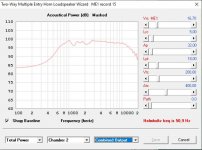
Vented woofer boxes, to me, is just another horn style. The proper way to use a horn is to have the tuning note, which governs cutoff, a specific distance away from the lowest intended note played.....if I tune my 18" woofer to ~15hz, Decay and Group Delay are significantly improved even before adding damping material into the design, so much so, that it begs to question...are people purposely sacrificing SQ for spl? If I tune to fs 24hz, performance in the 30hz area is bad with group delay and decay, though much louder.

A separate issue; lets put a huge resonance on top of the woofers resonance...who thought that was a good idea! Decay is exacerbated by the lack of control the woofer has at fs! let alone tuning too close to the passband.

I am focusing on 30hz, but as we move the register decay/group delay is improved as well.

Disappointed with my 300B PP build

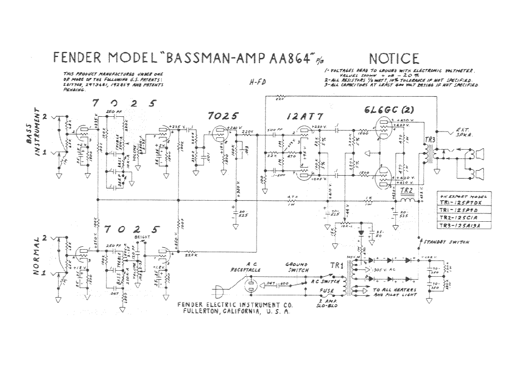
I've "upgraded" my 6B4G amp, a completely modded ST-70, to accept 300B tubes interchangeably. It uses the stock Dynaco transformers, the original choke in the power supply and the chassis. The driver board is a Curcio "premium" board that is spec'ed to use 4x6DJ8 as phase splitter/LTP, but I've been using 6N6P instead in the driver position. The main change with the power tubes is to remove the negative fixed bias and use cathode bias with 550R on the filament center tap. I also disconnected the negative feedback. Of course the UL tap just dead ends at the tube socket since the pin is open on a 6B4G. It really isn't hard to do the mod and make it work. The quad cap was replaced with a Curcio board that increases the capacitance with higher voltage caps and also nicely has bleeder resistors built in.

With the 6B4G tubes this amp just rocks, and can also play the soft stuff with finesse. I really had no complaints with it. And it has been stable too, no problems with it.

I modded it for 300B by removing the old unused cathode ground and the 10R resistor for the bias measurement. (the original I believe is 15.6R but you can't find them.) I then ran dropping resistors between pins 2&1 and 7&8. I wired adapters to take the heater voltage from 1&8 whereas the 6B4G uses 2&7. Each side worked when I tried it. So far, so good.

But what happens with the 300B in place is that when I turn up the volume one side drops out and doesn't come back when I turn it down. And not that loud either, just moderate really. (It is playing a lot louder than that now, We Will, We Will Rock You!!! So loud, but with the 6B4G). The PS is shared, so it isn't that. I have 2 theories. First, I don't have enough current to power both sides and one just drops. Second, the dropping resistors can't take the current through them. When I turn it off and back on both channels will play. And the 6B4G continue to work as always, so I haven't fried anything important. I haven't tried switching sides with the tubes but I'll do that tomorrow.

I'm also disappointed with the bass, but if I can't turn it up I won't get much bass anyway.

Any ideas? I get that I'm stretching an ST-70 beyond its limits so maybe I should just leave well enough alone and build a real amp.

Need HELP with compressor design

Hello everyone. I come here to seek help in the design of a compressor with a focus on mastering. I have two 6DJ8 valves and one of the requirements of the project is to use one or both of them.

Before I start, I want to make it clear that one of my goals is to minimize costs, even if it means worse sound quality - I'm doing it because it's a grad project and also for learning, but I don't have a decent budget at the moment, and the logistics and component production here is very costly and slow.

I developed a basic prototype in LTSpice to simulate with .wav files, and managed to compress drum sounds pretty effectively, at least in theory. However, I have no knowledge of the real, practical aspects behind it, and therefore I would like to receive help from the forum folk.


mOxfvOC.png

Some important points I would love to have contributions:


  • I want to avoid using transformers as much as possible (I know you can disagree with that, but tell me if it's possible to do it without transformers, or at least convince me why is it so critical/necessary).
  • The LED-LDR (in green) group represents a makeshift Vactrol I made with heat shrink, where the LED excites the LDR directly. I measured the set and developed its equation, which is under the LDR in the schematic.
  • I never saw an amp op buffer directly into the a compressor's input, therefore i feel in my guts this looks absurd in some way. Shed a light on this, would you?
  • The 6DJ8 uses 130V max plate voltage. As I live in a place where the electrical network is 127Vrms, I intend to rectify the signal directly to supply the valves. I heard about humming. Can I do it?
  • To supply the NE5532, I would like suggestions: switching source, voltage regulator... What is the most suitable solution?
  • The output represents an old radio output transformer (2400:8) and my laptop as load. How necessary is the transformer? Can I get rid of it? What are the implications of directly connecting, for example, my phone in the input and laptop in output?
  • I know mastering should be done in stereo. Can I just replicate this circuit for the Left/Right channels? Is there any (transformerless) other way?


Essentially: what works in this circuit? What is absolutely garbage? EVERY piece of information is extremely valuable. Feel free to contribute in any way. Thanks!

First time SMD Pre-amp

2020-03-22 15.09.55.jpg

2020-03-22 15.10.05.jpgHi,
At 64 with eye sight fading and shaky hands, I have had a go at my first pre-amp + phono stage since the late 80's. What a ball ache. Tried hot air gun and soldering Iron, but I am getting there, need tweezers and an eye class just to see the component. Went with SMD to keep size down as I only have free version of Eagle, hence modula design with many connecting cables...Just volume board to finish when parts arrive from Mouser.. Shocked at how much a few SMD resistors cost (thin film Vishy or Panasonic)..Hope images come out OK..


.
An externally hosted image should be here but it was not working when we last tested it.

Thoughts wanted on QSC SPA series amps

I noticed that QSC is producing a line of 2 or 4 channel compact (half rack) sized Class-D amps. Info:
Code:
Models:
          SPA2-60          SPA4-60          SPA2-200          SPA4-100
Stereo Mode Power:
8 Ω     60 W               60 W              200 W               100 W
4 Ω     60 W               60 W              200 W               100 W

Bridged Mode Power into 8 Ω & 4 Ω:
          200 W             100 W cont.     400 W               200 W
I scoured the spec sheets but I could not find any mention of distortion at any level. This has me concerned that spec is not very impressive. Maybe these amps are intended for commercial use where that is not a critical parameter?

Since I like to build active speakers, half-rack sized power amps are of interest because they could easily be incorporated into or placed on the speaker itself while remaining unobtrusive. An example of this is the Parasound Zamp. There are also some compact, modern 2-channel class-D amps from various Asian sellers, but I have not found them to have a very good looking distortion profile. There are mono amps like the Emotiva PA-1, but that is not really what I am looking for. Feel free to point out products that might work in this application.

looking for circuit to replace a home cinema amplifier

Hi

my home cinema is breaking down (it's an LG HX506DI which is blocked at startup with the message: "please wait") ... so I have in my pocession two speakers and a subwoofer that I would like re-use with another amplifier that I plan to buy used ... in the meantime I wonder if it is not possible to make an amplifier myself with the constraint: two kinds for the two speakers and one output for the subwoofer, a 2.1 input ...

Thanks

Decware issue

Hi just complete my Decware DIY SE84 amp and one side there is a issue.It plays ok for a second then slowly the volume falls to almost zero.I check the tubes,swapped tubes,cable,check the caps.Everything seems ok.The single driver tube by my tube tester indicates its weak.Could a single driver tube cause the inbalance of the channels volume?.

Choosing Parts Upgrade for Speaker Crossovers. Simple affair or a Nightmare?

A brief look at some Parts threads in this Forum involving Crossover parts has taken the wind out of my sails.

I thought it would be a simple task of carefully selecting replacement parts involved ensuring quality:

Inductors:
Select air core 16 gauge pure copper.
(avoiding iron core, thin gauge low purity copper winding)

Resistors:
Select quality examples which are non inductive.
(Avoid anything sandcast, and use of magnetic materials.

Capacitors:
Select quality examples avoiding cheap electrolytic designs.

After reading a few Parts threads on this subject I'm learning that there are almost as many variations on parts as there are Speaker manufacturers and Speaker models.

A nightmare to navigate.

I know variations can encompass, personal tastes, choice of musical source, equipment and loudspeakers involved which will play a part in making a selection, not to mention actual testing of performance.

For the simple enthusiast who is just looking for best bang for buck speaker crossover improvement, but isn't particularly technical and doesn't want to sink a kings ransom, is there such a thing as "go to" Capacitors, Resisters, & Inductors, not to mention binding posts (free of iron), which can make a difference to the performance of ones Loudspeakers?

Not only brands to choose, but a reasonably supplier?

cheers

Cliff

sony ta-n86b power supply help please

Being looking at this board for a few hours checked all transistors and change most diodes

i marked the voltages i am getting at test points

could anyone take a look and send me in the right direction..

most of the voltages are twice what they should be see attached

thanks so much for any help

Attachments

  • Capture9876.jpg
    Capture9876.jpg
    340.3 KB · Views: 113
  • Capture9876b.JPG
    Capture9876b.JPG
    224.8 KB · Views: 115

Can I use these jacks?

Not sure if this is the right area to ask this or not,but here goes.
I have this little 2.1 amplifier

TPS3116D2 Class D 2.1 Bluetooth 5.0 Amplifier Board 2 x 50W + 100W with Filter and Volume Controls

and this power supply

Amazon.com: AIYIMA 24V 4.5A 108W Universal AC Power Adapter Laptop Charger 5.5x2.5mm,Audio Amplifier Power Supply(24V): Home Audio & Theater

that I plan on putting in this aluminum case

Senmod 120x114x33mm Sliver White Aluminum Power Amplifier Enclosure HIFI Electronic Project Box Case - - Amazon.com


The case is longer than the board and I want to add a 5.5 x 2.1 jack to the back panel of the case so I can plug in the power supply. The amp has + and - power terminals so you can add an external jack. I found the ones below but was worried that I couldn't use them because they will ground to the aluminum case.

Amazon.com: Lsgoodcare 10Pack 5.5 x 2.1 MM 5A DC Power Jack Socket Threaded Female Mount Connector Adapter with Dustproof Plug: Home Audio & Theater

Is that going to be a problem? There are jacks available with plastic casings as well, but most of those say they only handle 3A. Does anybody think that will be a problem using the plastic ones because of the lower amp rating? The board for the amp seems to have a pretty cheap plastic female plug so I didnt think the plastic ones would be any worry.

Thanks

Fun to-do list while C19 runs its course

Make a list. You probably can't get everything completed but it's a plan.
My list:
Three st70 chassis need to be rewired and tested.
Finalize tube hybrid design.(using only parts on hand)
Minimus7 speaker stands.
Combo guitar amp of my dreams.
Finish stereo plate reverb.
Learn how to play harmonica.
Finish quantum action at distance experiment.
Update password book again.
Build boombox with some of those $2.00 tpa3118 amps bought years ago.
Become proficient in f150 hacks using forscan.
Repair the stack of Marantz receivers collected.
Find better solution for music software, start re-ripping bucket library. (nursing home version)
Update the buried hard drives.(field trip)
Get ham station back on air.

This list is probably good for a 90 day pandemic.

Various Class AB gear for sale

Hi, I have some Class AB gear to sell. As a newbie, my eyes and pocketbook were bigger years ago. I will not be building the attached kits, boards, etc. Prices are marked at a good discount already, but all offers considered. Shipping is not included. Shipped from Western Canada.

Image 1: Destroyer Dx Super A w/coils
Image 2: Dx regulated PS.
I have 2 sets of these (2DxSA+1DXPS / set): $50usd per set

Image 3: My Ref FE v.1.05
I have 2 pcb: $30usd for 2 pcb

Image 4: VSSA amp module, components installed list, build guide
I have 2 modules: $60usd for 2 modules

Image 5: CFH9 amp Apex/xrk971/Sonal
I have 2 pcb: $20usd for 2 pcb

Image 6: P30ZF pre amp Apex/alexmm
I have 4 pcb (2 needed per preamp) $10usd per set of 2

That's about it for this advertisement. PM if interested. I will be advertising more gear also, so keep tuned.

Regards,

MylesDx Super A.JPG

Dx Reg Supply.jpg

MyRef FE v1.05.JPG

VSSA pcb with components.JPG

VSSA document.JPG

CFH9.JPG

Apex P30ZF preamp.JPG

3 way design help with a ribbon tweeter

Here is a list of my components id like to use. Im not sure how well this pre-made 3 way crossover is but the 4500 cross with the tweeter seems good to me as with the rest.

Peerless 830990 6-1/2" GFC Cone HDS Woofer 8ohm
Peerless by Tymphany 830990 6-1/2" GFC Cone HDS Woofer
Peerless 830992 4" GFC Cone HDS Woofer 8ohm
Peerless by Tymphany 830992 4" GFC Cone HDS Woofer
Fountek NeoCD1.0 ribbon tweeter 5ohm
Fountek NeoCD1.0 Ribbon Tweeter
or this tweeter 7ohm
Fountek NeoCd3.0M-blk 3" Ribbon Tweeter - Round Flange - Black

Crossover
Speaker Crossover 3-Way 8 Ohm 800/4,500 Hz 200W
or
Eminence PXB3:3K5 3-Way Speaker Crossover Board 500/3,500 Hz

my other issue is wiring since the tweeter seems to be 5 ohm and the other two are 8ohm. Not sure how that will workout. I also wanted to build a center speaker with one more 6.5" driver.
Any help or recommendations on if this will work?

Good budget tweeter for HiVi F6

Hello everyone, hoping all is safe.


A friend of mine recently gave me a pair of HiVi F6 drivers which I plan on building powered bookshelf speakers out of.


I am looking for a good budget tweeter, preferable around or under the 30 dollar range. A couple of options I was looking at are the Morel MDT12, Morel MDT22, Dayton Audio RST28F-4, and the Dayton Audio DC28F-8.


What do you guys think, any suggestions?

Much appreciated

Dynaco A431 output stage voltage swing

What is the measured voltage swing peak to peak on steady tone 1KHz needed to bring a push-pull 6550/KT88 pair of tubes in UL connection with A431 output transformer?


Power supply B+ is 500Vdc
Each tube bias at 50mA


Question arised from measurement of a mono bloc Dynaco MK 3 and pushing only 40 Volts peak to peak at onset of visible clipping, on 8 ohms tap with a resistor.
Should go near 60 V p-p ??


Driver stage is a Poseidon with new tubes 12AX7, 12BH7
Outputs clips before the driver stage shows clipping measured at the input 6550 KT88 grid.


Thanks.

[First Build] 3.5 Way Speaker Design + Crossover Help

I'm looking to build a pair of floorstanding 3.5 way speakers with the following components and would appreciate any feedback.
My goals are some amazing sounding home theater floor standing speakers that will be used 50% for movies and 50% for music.
I have a Velodyne SPL-1200 Ultra subwoofer so won't need the speakers to give any rumble during films, but would like them to cover as much of the 20hz - 20khz range as possible as I like to listen without the sub for music generally.

I've picked Dayton Audio Reference drivers as I've been recommended them as brilliant quality drivers.

Tweeters: Dayton Audio RST28F-4 1-1/8" Reference Series Fabric Dome Tweeter 4 Ohm

Midrange: Dayton Audio RS52FN-8 2" Reference Fabric Dome Midrange 8 Ohm

Bass: Dayton Audio RS225-8 8" Reference Woofer

I've never designed a crossover before so any help would be greatly appreciated.
  • Like
Reactions: nlRenderman

Chassis parts, power entry, switches, terminals, RCA, Speaker, etc.

One of the hardest parts of DIY amp building, for me at least, is rounding up all the miscellaneous parts to make things work in my chassis.

At places like mouser, there are literally hundreds of thousands of these parts. I live in a remote area and don't have a place to go "look" at parts to figure out which ones I would like best.

So I thought I would start a thread to get input on your favorite miscellaneous chassis parts. There are no limits to what you suggest, but a few items that are always necessary. Would be nice to list the mouser or other location part numbers.

- power entry connectors

- power switches

- power fuses/holders

- terminal strips/blocks to mount on the chassis for various components like an NTC or other external parts.

- Switches of many different types, input selector switches, bias meter switches, etc.

- Meters for things like bias, other settings, power meters, etc.

- RCA connectors, speaker connectors, etc.


What are your favorite misc chassis parts? If I can get a good list going, I'll create a mouser project and share it out for others to use/copy.

gabo


I'll start off by offering this link:

Keystone Electronics Lug Terminals Terminal Strip Solder Terminals | Mouser

It took me a while to find these on mouser, but find that I use some variant of these on almost every project.

DHT filament voltage vs current??

I am playing around with some 12As in a preamp and i have noticed something odd:

I use a LM317T as current regulator for each tube (two separate LM317Ts plus separate floating PSUs). The CCS are adjustable so I set each one for 5V measured at the valve pins.

However current through both valves is 297mA?? I experienced the same with a 71A I plugged in...

Input to the CCS is 12V. The LM317Ts have ~4V across them so they are not dropping out. The voltage across the sense resistor (10R in parallel with 390R and a 1k pot) is 2.88V. Both filaments measure 5V

What gives? The spec for both 12A and 71A is 5V at 250mA....?

Quick question on RCA interconnects

Looked around a bunch on here and think I have my answer, but just looking for confirmation.

I'm trying to make a pair of longish RCA cables to add a second zone to my stereo. It's going to run through the basement so I received Canare star quad cable as a recommendation to keep out the interference.

I read a couple of threads on here about how to construct these properly and have one last question.

Of the three wires, signal (Blue), return/drain (white) and shield (braid), which one do I leave unconnected at one end of the cable? I've read posts/articles that say the drain should only go one way, but most of what I've read said the shield should be the wire left floating.

Thanks!

Parallel Capacitance (cables).

Admin: If this thread is located in the wrong section, please move it.

Alright, I am experimenting with some cable design and got to the part of measuring parallel capacitance (Cp) and realized I am missing some information.
When we read the shared information from cable manufacturers, Ls, Cp & DCR is often shared.

My question is this: I understand that Cp is measured between 2 leads with one of the ends open, but that is not what I am wondering about. Say you have more than 2 conductors (typical), each conductor pair has Cp.
Am I suppose to only look at the Cp between one pair or am I suppose to add all the pairs together ?

Ex): There are 5 conductors, which amounts to 4 pairs, so: Cptot = C1+C2+C3+C4

Many thanks in advanced.

Oneminde

Adding a stereo input jack to bluetooth headphones

Hello all! Hopefully this hasn't already been posted about, I couldn't find anything using the search.
I recently acquired a pair of OneAudio Studio Wireless M headphones by accident. I got them as an open box for super cheap and didn't realize they were a bluetooth model with no input jack. They were so cheap it wasn't worth shipping them back, and they actually sound decent enough for the price. I figured theyre good for when I'm doing homework and I don't have to worry about breaking them if I toss them in my backpack for school.

That being said, I'd like to add a wired option to them so I can use them if the battery is dead. I've never dealt with bluetooth so I was wondering if you could provide some help. I'm assuming the receiver must have output wires to the drivers that I could solder the jack to. What I'm not sure of is if I need to add some sort of switch to change the source, or if just having the headphones shut off when I plug them in would be sufficient.

I think this should be pretty simple to do, I'm just still learning about how electronics work so I thought I'd ask the pro's. I figure its also a good pair of headphones to play with since they were super cheap and if I mess something up I won't be out much. Thanks in advance!

Par-metal headphone amp chassis w/ FPE panels

Nice aluminum chassis for a headphone amp project.
My RJM Sapphire was in this chassis. PCB's are sold and I'm parting out the rest.
Chassis is in generally good condition, bottom has drill holes from previous project.
Front and rear panels by Front Panel Express

- Dimensions: 7W x 12D x 2.5H
- Front panel - holes for volume pot and headphone socket
- Back panel - holes for RCA. New IEC and used SPST fitted.
- Bottom - 3M bumper feet

Case costs around $67, panels another ~$50, IEC, SPST etc....

Asking $45 + shipping

P.S I haven't verified all dimensions but I think a WHAMMY with offboard pot can fit nicely

Attachments

  • 2020-01-28 23.40.33.jpg
    2020-01-28 23.40.33.jpg
    405.1 KB · Views: 468
  • 2020-01-28 23.40.52.jpg
    2020-01-28 23.40.52.jpg
    238.4 KB · Views: 472
  • 2020-01-28 23.41.03.jpg
    2020-01-28 23.41.03.jpg
    227 KB · Views: 473
  • 2020-01-28 23.41.17.jpg
    2020-01-28 23.41.17.jpg
    361.6 KB · Views: 467
  • 2020-01-28 23.41.40.jpg
    2020-01-28 23.41.40.jpg
    311.8 KB · Views: 455

PCB layout for "constructive" criticism

I've designed many complex digital layouts but never anything analogue and certainly not valve.

I've created a PCB layout for the RH84 design amplifier and would appreciate comments on the layout. I've attached two versions: the basic layout, and one with a ground plane copper flood - something that is routine for digital.

The layout is single sided with no jumpers needed. The heaters are not included as I would intend to wire these separately with twisted paired wire routed away from the PCB. The PCB size is 100x200mm which is the size of the blanks I happen to have available. All HT traces have a separation of at least 2.5mm from any other trace which should be good for 315VDC without solder resist.

All comments appreciated

Image1 — ImgBB

Image2 — ImgBB

Horrific noise from ICEpower based amps :-(

First post here so, please, be gentle.

I have two April Music S1 stereo/mono power amps that had been humming along nicely for several years. The amps are based on the ICEpower 250ASX2 module. I've been using them since new in the mono configuration.

Several months ago, one of the amps started producing a horrendous noise when switched on. I was sure it was going to blow out the Esotar tweeter in its corresponding speaker. Thankfully, it did not.

I took the offending amp out of service and switched the other amp to the stereo configuration. That was fine for a while. Incredibly, about a month after the first meltdown, the second amp experienced the exact same failure!

With April Music out of business, there's no manufacturer's safety net in place.

Since so many forum members have experience with class D modules it seemed like a good resource to turn to for advice. While there is additional circuitry inside the S1 amps, I can't help but think the noise is most likely originating with the 250ASX2 modules. Is that a reasonable assumption? Replacing the modules would not be that difficult (expensive, but not difficult).

Yes, it is VERY curious that after years of service the two amps would fail within months of each other. Don't know what to say about that. I've replaced them with a pair of Schiit Vidars (in mono mode) and those amps have had no issues despite having been dropped into the exact same equipment setup as the April Music amps.

Any thoughts, suggestions, recommendations would be greatly appreciated.

Little help identifying this AlNiCo driver

I have the frame and magnet of this old 8 inch AlNiCo speaker that I got from I friend of mine. Its cone was destroyed so I cleaned it to rebuild it in the future.

However, I have a single one and I wanted to have a pair. And I'm trying to figure out what speaker it is to find a similar or equivalent one online.

Here are some pics:

qlUv3hP.jpg


FuP48II.jpg


My59vEz.jpg


sHXPkpm.jpg


As you can see its remarkably similar to Philips 9710, but it isn't a Philips 9710. There are some differences, as, for example, the fact it seemingly uses a brass demodulation ring (and in a different placement) and the "holes" in the frame are completely round, while 9710 had holes with flattened sides.

I remember the original cone (although damaged) it had a whizzer exactly like Philips 9710.

It has these numbers and codes behind: "KF 239" (with an indiscernible number ahead, but looks like a 10) and "326", none of which gave me any results.

This speaker was found inside one enclosure of a used stereo vinyl player, and I don't know if this is the original speaker. The speaker in the other enclosure was a different AlNiCO speaker.

It was bought in Brazil but I doubt this speaker was built here at all.

So, any ideas?

Do you think that If I bought an used Philips 9710 I could rebuild both to be reasonably matched drivers?

Thanks!

Trying to understand PSU vs Amplifier and headroom.

Firs do I have to tell that Mooly have already told me how to construct a power supply for his amplifier. What I am trying is to learn and understand the PSU thingy🙂
I do not learn by just copying and not understanding what is going on.


Let me start by telling what I think I may have understood.


1) A power amplifier do have a predetermined gain-multiplier, a multiplication of the input signal, that are the result of the construction and is not adjustable.


2) If the power supply's Voltage is less then (input signal x gain) you have clipping.


3) headroom do let the amplifier avoid clipping if the input signal, suddenly gets higher, due to suddenly change in input signal.


My question is first, is that right?


Second input signal x gain must have an upper "real world" limit, a limit for how high an input signal can bee?


If we take Mooly's amplifier, since that is what I am building for the moment. It have a recommended input Voltage of 45V p/p but what would 100V do (assuming all component can handle it) Would that give headroom, general higher gain or just stupid?


Please if you want, do try to explain it so even an dummy can understand it🙂

Alpine MRP-M450 repair help

Having some trouble with this amp, when I give it +12 on the remote the amp tries to pull what I assume is excessive current. (I have my bench top power supply set to 3 amps.) The power supply will pulse on and off trying to build rail voltage but not achieving it. I never get a square drive wave on the gates.

I removed the rectifiers, the power supply no longer pulses and the amp only draws a little bit of current on start-up. There's a good drive wave on the PS gates at start up but it disappears very quickly and the current draw falls back to near zero.

The rectifiers tested OK; no shorts, not open, passing current in the correct direction.

One of the output FETs is no good, the other 3 check out OK on my multimeter. With the outputs pulled from the board and the rectifiers back in the amp returns to a state of pulsing, failing to build rail voltage.

The only components generating heat are the PS FETs which get warm but I also have not left it running for more than a minute.


Does anyone have a suggestion of where to look next? I was not prepared to find a TDA7570 driving the outputs. :warped:

Attachments

  • unnamed.jpg
    unnamed.jpg
    728.4 KB · Views: 183
  • unnamed (1).jpg
    unnamed (1).jpg
    927.1 KB · Views: 232
  • unnamed (2).jpg
    unnamed (2).jpg
    805.3 KB · Views: 189

Opinion on a first 3 way crossover

Hi

The DIY speaker bug got into me about two year ago and, unfortunately, the more I read, I felt that the less I knew... Now with far too much time on my hands, I decided to give it another go. Yes, I understand that a 3 way speaker is much more difficult to develop and I would be better off with just buying a kit, but where is the risk in that 😀

Drivers used:

Dayton Audio DSA315-8 12" Designer Series Aluminum Cone Woofer
Dayton Audio RS52AN-8 2" Reference Aluminum Dome Midrange
Dayton Audio PT2C-8 Planar Tweeter

I tried to maintain a flat curve and an overall impedance over 4/5 ohms (my past attempts would just dip to 2 ohms or lower).

What I do not understand:

a. Regarding the phase graph.. Are the vertical lines supposed to overlap in order for the drivers to be in phase (I assume in phase electrically, as they can be out of phase depending on how I place them on the baffle)

I was hoping I could have your opinion regarding the crossover/ the feasibility of my design.

Thank you

Attachments

  • Test3 Six-pack.png
    Test3 Six-pack.png
    127.5 KB · Views: 210
  • Test3 XO-schema-1.png
    Test3 XO-schema-1.png
    20.6 KB · Views: 229

A, B or C and why?

I've got an amp project going on another thread here. In that project I want to use a TV horizontal sweep damper tube as a "slow start" device for the B+. Currently I have option "A" in that schematic. But I was thinking... if the purpose of the damper is only to give me a slow B+... Why the heck am I putting it right behind my silicon diodes? It can be anywhere right? So I drew up options B and C in the picture. I'm liking C the best but want to run it past. Moving the damper down the chain allows me to use a much larger first filter capacitor (option B). But then I thought why not get a lot more filtering capacitance by moving the damper to the end of the whole train? (option C). All options have the same number of capacitors, just in different places (MRC is motor run capacitor as I wanted to end the filter train with a film capacitor).

Which do you like the best? Am I way off on something here?

Attachments

  • PowerSupply.png
    PowerSupply.png
    81.6 KB · Views: 234

Best replacement for black gate 100uF N 50v cap

I just recieved new from partsconnexion that they have sold out of black gate N 100uF 50v caps. This is very unfortunate as I was planning to build a parallel version of Peter Daniels gainclone (using his pcbs). I have a stereo version up and running and it is wonderful with the BG N caps - they were a big improvement to the standard panasonics supplied in the kit. Now I can't source similar parts and it seems that I will have to build a parallel version using other caps. It is rather frustrating that BG are discontinued as they really have improved the sound in my alephs, preamp and my DAC...

1.
Are there any caps that have similar sonics to the BG N cap?

2.
Would parallelling a BG standard with a smaller value of BG N or film cap be a good approach?

3.
Would it be possible to use 70uF instead of 100uF? As in one very big film cap. (so long for the small enclosure)

Thanks for any answers.

Memphis PRX1.1500

Hi guys,
I have this Memphis on the operating table. The symptoms are protection light and power light are both on. I pulled the outputs to see if protection light would go off, nope. I pulled driver board, no help there either. Pulled the power supply FET's, that wasn't the answer. Has anyone ran across this before?

Attachments

  • 20200411_174542.jpg
    20200411_174542.jpg
    873.9 KB · Views: 136

Music server/streamer

I’ve made a very good 3eAUDIO TPA3255 amp with an analogue input and I am thinking of making something a bit more high tech next. I’ve done some some research into components and figured I could build this into a small case.

A tiny windows 10 pc with WiFi, hdmi and 2 usb’s.
5” Touchscreen
Khadas dac
Audirvana software or similar
USB SD card reader

I know I could get it to work but does anyone think I would be able to get the user interface configured to work well.

845 SE power amp need suggestion and some technical information.

I hope to build a (one tube) 845 SE amp,
25 watt power output, frequency response 18 to 22,000 Hz, +/- 1 dB.


20 Hz 25 watt power output under 3% THD. someone did it before?
Which output transformer can meet to this specification?

16K, 18k or 20K

Triode / Pentode Loadline Simulator (v.1.0 20161216)
give a curve
Ra =19.4K ohm
Total Harmonic distortion 2.033 [%],

If custom made this 19.4 k ohm transformer, this project will workable?

please get me some suggestion, I really hope to build a 845 SE amplifier 25 watt power output running on 20 Hz, total Harmonic distortion below 3%.

Attachments

  • 8451.png
    8451.png
    151.3 KB · Views: 137
  • 8452.png
    8452.png
    38.8 KB · Views: 134

Mark Levinson Drive problem

I am working on a newly acquired ML 39. Drawer opens, but does not close. After drawer is in open position, display shows "add disk". After loading disk and pressing "Play" or "close", drawer does not move and display only shows "close" while holding the "Close" button. If I manually close the drawer, display shows "Stopped!" and upon pushing "Play" shows "Drawer?".
Laser unit does not spin CD, but laser is moving, however, with some "ratcheting" noise. I know that a service manual is unobtanium but perhaps someone here can point me in the right direction, i.e. supply voltage to the Philips CDM12 unit, other voltages required, timing sequence for the drawer etc.
I searched the archive on this forum, but could not find adequate information.
Many thanks in advance.

Help Interpreting Scope Measurements

Hi all — trying to improve my very limited technical understanding. With my F6 amplifier, I have a very faint hum in both channels, but more pronounced in the left. I previously had an F5 in the same chassis, with the exact same observations. I finally measured both channels with a scope and got the attached two results — a fairly clear peak to peak sine wave of about 4mv in the left channel, and a bit of a hash in the right. These measurements were taken with the F6 inputs shorted and with no load. Connecting the input rcas made no difference in the readings. My best guess is that this is induced mechanical hum from the transformer — not a ground loop — but does anyone have the time or patience to explain to me how to interpret these measurements (or, even better, capture more meaningful ones)?

Overall, there’s nothing wrong with the amp. It sounds wonderful, I’m just interested in learning more.

Thanks!

Attachments

  • 9EA6E321-0C82-4D1F-BBD1-B68E5E3A1A0F.jpeg
    9EA6E321-0C82-4D1F-BBD1-B68E5E3A1A0F.jpeg
    341.1 KB · Views: 112
  • EC936658-96B4-4DF1-8B2E-22D179802F3C.jpeg
    EC936658-96B4-4DF1-8B2E-22D179802F3C.jpeg
    321.4 KB · Views: 121

EL34 Tube Amp Modification Advice

Hello All,

Thanks to all of the useful help from this forum earlier, I was able to resolve all of the issues with my tube amp. I got some new EL34's and rewired the preamp socket to run a 12AX7 and it sounds amazing. Pure SE bliss.

Here are the previous threads I posted:
https://www.diyaudio.com/forums/tubes-valves/351067-help-6n2-el34-tube-amp-kit.html
https://www.diyaudio.com/forums/tubes-valves/351256-regulating-filament-voltages.html

All of the issues in the previous threads were solved. My filament and bias voltages and currents for the tubes were all within range.

In designing an enclosure, I did run into a few questions I had and figured you folk would be the best to consult with.

1) Extending the Tube Sockets
2) Improving the Bass Response
3) Powering the VU meters with the filament taps on the power transformer.

I did a little research on all of the topics, and these were the recommendations I found.

1) In extending the tube sockets, if I read correctly, the grid stopper resistors need to be close to the tubes to work effectively. Would it be a better idea to run a jumper on the PCB and solder the grid stoppers between the tube base (that will plug into the PCB) and the panel mount socket? I also saw a thread where a 100 ohm resistor was soldered in line with the grid extension, leaving the grid stopper in its initial location.

2) In expanding the bass response, I have read that the OPT and coupling capacitors are the main factors in determining the bass response. My coupling capacitors from the 12AX7 to the EL34's are 0.47uF currently. I was looking at replacing the OPTs with two of these:EDCOR - XSE10-5K, but I would like to see if there's anything else I can do before ordering a pair.

3) I was looking at adding a voltage doubler circuit through the filament supply to power the control board for my VU meters. Would this introduce any noise/distortion to the heaters? I read that there is a possibility of frying the diodes if the DC side of the circuit is connected to ground, but my 6.3V does not have a center tap, so would it pose an issue?

Attachments

  • Schematic - Updated Pinout .jpg
    Schematic - Updated Pinout .jpg
    625.6 KB · Views: 460
  • Parts List - Amp.jpg
    Parts List - Amp.jpg
    407.4 KB · Views: 419

NAD C720BEE (C320BEE) fixed.

Hi.
I am French.
Excuse me if my English is not very good.

I own a NAD C720BEE.
It does not work anymore.
I did not use it for several months.
He was, all the while, in standby mode (amber light).

The breakdown is:
- VACATION SWITCH ON/OFF -> ON => POWER/STANDBY/PROTECTION LED -> AMBER.
- POWER Button -> ON => POWER/STANDBY/PROTECTION LED -> stays AMBER, but i hear, after a few seconds, some clic on some relays.
- The TROUBLESHOOTING GUIDE indicates : CHECK THE 12V POWER SUPPLY CIRCUIT.

I have not +12V, on E-Q413 (J123 (12V)), because i have not +18V.
The +18V is generated from the +37V.

For information, the value of +/- 46V (V+, V-) are +/- 37V. The power supply is, therefore, in degraded mode.

The VFD board is OK.
The Reset (FM + CD) is OK.
The Software version ("FM''+"AM") is V 1.03.

After investigation, R45 (33 Ohms 1/2W) is broken (no +37V on C-Q41)
R45 was broken because C49 is in short circuit.
Becarefull: the schematic indicate : C49 47uF/ 25V, on board it’s a 47uF/50V.


Good luck.

Loubine.

Power consumption Sure/Wondom AA-AB32313 2x400

Hi,

does anybody know the _idle_ power consumption of the Sure/Wondom Electronics AA-AB32313 2x400 or AA-AB31511 1x500?

In the datasheet I find values up to 25 W (!). I think, that is very much for an class D Amp and I can't believe it.

My 7498E with stock power supply takes approx. 2W. Sure, it's smaler but not 10 times.

I would be very glad if someone could post his own measurements.

Mini Sub inspired by PC Voxel

Hey guys, I just designed my first Subwoofer based very loosely off of Paul Carmody's Voxel speaker. I am using the Tang Band W5-1138SMF 5-1/4" Paper Cone Subwoofer Speaker paired with a Dayton Audio SA70 70W Subwoofer Plate Amplifier.

The enclosure is has a volume of 12L with a tuning frequency of 34.5hz. This is accomplished with a 1"x 6.4" slot port that is 32" long. All this allows the F3 to 30hz and port air velocity to never exceed 17m/s even at the amplifier's max wattage. I plan to build the enclosure out of 3/4" MDF for the extra rigidity.

My one concern is cone excursion. It will reach its X-max at it's F3 frequency. However I saw that Paul's design does the same and starts reaching Xmax at his F3 of 35hz. Will this be an issue? This is only an issue when running the sub at full amp output though, so I am guessing it should be fine.

I'd love to hear what you guys think before building the box. Tear me apart 🙂

Taramps HD5000 RC Network question

I’m working on a Taramps HD5000 that smoked both of the metal film caps at the speaker output terminals.

Taramps used 400v caps in this location. I don’t have any 400v caps in stock. I was wondering if I could go back with 250v caps. I’m not sure what determines what cap values is used in these RC/zobel networks. I’ve worked on lots of these Brazilian amps and have several in the shop at the moment and they are all different as far as the style and value of caps used at the speaker terminals.

Could someone enlighten me a little.

Thanks,
David

Attachments

  • image.jpg
    image.jpg
    973 KB · Views: 111

VPI resto-mod...a tale of bastardizing my HW19

I have enjoyed being a member of DIYAudio for a decade now. In that time many members have inspired and helped me. I’d like to share this project with the hopes of possibly doing the same for someone else.

When I decided I wanted to pull my record collection back out after many years of storage, I didn’t know what to do about trying to put together a decent quality playback system. All I had in my possession was a cheap generic Technics turntable that didn’t work anymore. After a lot of hours researching and reading on the net I ended up with an old used HW19 MK2 off of eBay.

There were a few things wrong with the HW19. Some bits were missing from the spring suspension and of course there was no tonearm and an unusable tone arm board, but all and all it was in decent condition.

I fixed the suspension and fabricated a plywood tonearm board for it. I also fixed one of the corners of the plinth that I noticed had separated a little.

I found an affordable rewired Rega RB250 on Audiogon, mounted it with a Clearaudio Virtuoso I got on sale and was off to the races.

Almost immediately after the table was playing, I found one of the early VPI speed controllers cheap and added that to the table. I verified speed with a inexpensive hand held digital strobe I found online.

A 16.5 record cleaner showed up as a Xmas present along with some new vinyl that year.

Life was good. I was very happy with the table and enjoying my vinyl collection more than ever. I used it with an Audible Illusions 2D preamp, Counterpoint SA12 amp and my old KEF 104/2 speakers.

Of course this wasn’t actually as easy as it sounds. The cost of all this equipment added up, and I had been sucked back into a culture that wasn’t very different from what I had spent many previous years doing...building, modifying and racing cars.

So this is the story of my eventual journey “down the rabbit hole” so to speak with my turntable. I’m sitting back again now and finally enjoying music after over 9 months of not being able to spin vinyl. I won’t be able to post all the pictures and descriptions at one time, but I will try to keep adding info and more pics. Every story has to have a beginning, so I’m gonna kick the thread off with a picture of my HW19 pretty much as she sat for about 12 years.

Attachments

  • 753CFC10-6FF1-48A6-BEE4-EE808FDB4215.jpeg
    753CFC10-6FF1-48A6-BEE4-EE808FDB4215.jpeg
    290.9 KB · Views: 793

Tri amped amplifier?

Well. I am totally new to audio things and I recently build a pair of speakers to use as my studio monitors, talking with the friend that helped me to build it him told me that I will need a Tri amped amplifier, but I didn't find any amp searching for this, I have a 10" sub, a 3" mid and a 3" tweeter, they're all 8ohms, so I need a tri-amped amplifier that can power them, do you guys know any thats budget?

TSE must die .... not yet

Hi folks, I'm Giuseppe writing from Madrid.
Yes, struggling with Covid-19 and locked up at home.
I have a TSE and happy with it from....maybe 7-8 years.
Maybe the virus, maybe don't know what, the thing is that a couple of days ago I was listening music from my loved TSE 300B when a channel said : puuf and stopped music. After that R14 begun to smoke....
To make a long story short, after some measurement I thought that Q1 was bad and replaced it (probably after so long a screw released and Q1 lost connection wirh heatsink.
Made all the checkout following instructions, put on 300B, speakers on......no music from one channel and very strange measurement....I was measuring R19 - R29 and the value from "bad" channel was out of measure (one channel : 65mV , the other : 6V) ..... stop all, off the tubes, check again.

Attached is a photo with measurement I have today....I think all is OK so muy next guess is that one of 300B is bad.

What do you think?
Is there a way I may check a bad 300B or next steps?

Many thanks, and thanks George for TSE-II.

Best regars all

g.

Attachments

  • TSE-measure.jpg
    TSE-measure.jpg
    377.6 KB · Views: 403

Has anybody made an ELS headphone?

I am making an ELS headphone. So far I am biasing it at around 1200V. But yet, the sound is still too soft. I am using a 6L6 SE tube amp to drive it though. I wonder if I were to use a more powerful amp to drive, will I get louder sound?

By the way, my spacer is 0.5mm and I am using "food plastic wrap" as diaphragm.

Attachments

  • 23102008648-small.jpg
    23102008648-small.jpg
    35.3 KB · Views: 4,808

Need Bluetooth Nixie tube harnesses

Hi all,

I have a project that I was wondering if anyone was interested in providing a turn key circuit for. I need a source of supply of a simple circuit to drive a bookshelf Bluetooth speaker. The circuit needs to be Bluetooth capable, battery powered, uSB charging for battery, two speaker, but the kicker is I’d like to use a 0-9 Nixie tube as the volume indicator. I’m not a true electronics engineer and I don’t know if this is possible, but I’ve got 1000s of nixies in various shapes, and I’d like to make a mid-priced somewhat steampunk looking portable speaker. Looking to buy a working prototype and then buy complete harnesses.

Best regards,

Sid-

DOA - Discrete Op Amps

Composite Tube-Opamp dual Dip8

well it’s official, i have the doa bug.
i’m doing it with a classic opamp mounted/combined with sub miniature triode.

Edit 10-2018 : I've learned a great deal during this project and now taking that knowledge to the next level.
So there will be no more updates from me on this fantastic concept. Thanks to Brent Butler for publishing it in 1998.
-Bruce
Projects by fanatics, for fanatics
Get answers and advice for everyone wanting to learn the art of audio.
Join the Community
507,669
Members
7,883,453
Messages

Filter

Forum Statistics

Threads
405,990
Messages
7,883,453
Members
507,669
Latest member
dukerd74