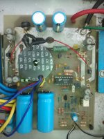
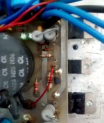
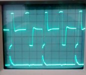
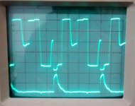
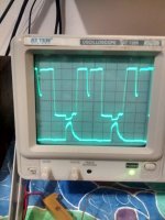
I have an amplifier that seem to be working properly but get very warm and is very inefficient. The SMPS is a bit unconventional it has a pot core with four Tip35c NPN transistors switching the supply everything seems to be working fine except for the pot core. The waveforms measured seems like inductance leaking I’m not sure Can anyone tell me why these waveforms look like this? The top waveform is across the inductor the second waveform is at the base of transistor. Why does it look like this? Push Pull +/- 36v First picture is idle the second is 5A and third is 10 Amps.
Attachments
Last edited:
I presume its an H-bridge driver to a simple transformer? Diode across each transistor?
The first image looks fine - the base switches on, the current flows, the voltage drops to zero on the collector, then on switch off the voltage kicks back till one of the diodes conducts (fast-decay mode).
The second image shows the storage time is much larger (higher currents?) so switch off is delayed - very normal for BJTs,
one of the reasons MOSFETs are much more efficient.
The last image shows the kick back from the previous opposite cycle hasn't finished before the transistor you are monitoring switches on.
I think its fine from switching point of view (though there's no clue of actual us/div, which might be important).
The only thing that might happen to a ferrite core over time is a loss in permeability, especially if running very hot, but there's nothing in these waveforms suggesting a problem to my mind.
Last edited:
BTW the TIP35C is not designed for switching, its an _extremely_ slow device, probably taking many microseconds or even tens of microseconds to switch off. Doesn't even have switching parameters in the datasheet.
No this is a normal Push-Pull configuration it pulls it down the goes back up like its leaking inductance I have not included the other pulse but it is 180 deg from that one it pulls it up and shoots back write down maybe the core is not wound correctly or it has a gap