Hi !
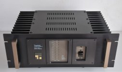
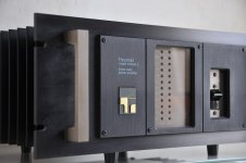
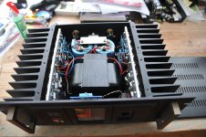
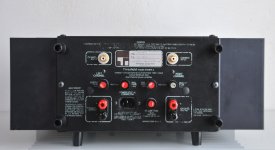
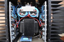
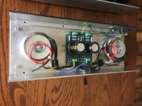
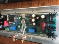
I was recently given a DUAL CT 7030 FM/MW/LW radio receiver to repair.
I do have some knowledge on electronics, but never worked on any radio receiver. This was my 1st try, hopping I could learn something. I'll try to explain the problem I'm facing, and all the steps that took me there ... most likely, I'll describe a lot of incorrect things, but like I said, I'm trying to learn
🙂
When I got the receiver, everything powered up ok. Only static noise on FM band, and absolutely silence on everything else.
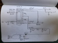
I was able to find the schematics, that I'll include later on, as well as the alignment tables. All power rails were ok, so had to look somewhere else. Probing on TP1 , I realised that the voltage was always above 9V, no matter the frequency I tried to receive on FM/MW/LW. At first, I thought it could have something to do with the PLL (IC601 SAA1057), changed the PLL, XTAL and in-series capacitor, but didn't solved the problem. So, I decided to isolate the FM from MW/LW tuning stage, and I started to have some voltage change (VCO) on MW/LW, but not on FM.
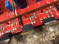
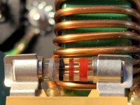
After some more poking around, I found out that the dual varicap (D4 KV1310) was bad, so I replaced it. Also tested the dual gate mosfet (Q1 2SK74) outside the circuit, and the Vgs was happening at random values (might be my testing skills ... don't know), but I also replaced it. After all those changes, there was some "life". I was now able to tune some FM stations, and even in stereo ... but, the auto scan feature couldn't pick a single station. That was when I realised that someone, before me, was already messing around with a lot of the variable tuning coils and capacitors
🙁
I never aligned a receiver before, I don't even have the right equipment ... or the right knowledge ... unfortunately. Even so, I tried something: tuned to a noise free station, and varying T102, I got the voltage between TP2 and TP3 to a value close to 0V. At this time, the auto scan feature, started to work
🙂 Just a small (big) problem. All the stations, I can only tune 100KHz above, this is, if the station is 98MHz, I can only tune it in 98.1MHz ... and this is all over the scale.
I was also poking around with L10 (it is actually L16 on the schematic, the actual L10 can't even be changed!! ... the schematic is very imprecise), to be able to set the VCO voltage coming from the PLL. But there is only one component to adjust it, and if I set the upper value, the lower value drifts as well.
Example:
If I set: 108MHz to 8.50V, I get 87.5MHz at 2.34V.
If I set 87.5MHz at 2.50V, I get 108MHz at 9.83V
(please see the alignment table in attach)
.. I ended up shooting for the middle: 9.17V at 108MHz and 2.37V at 87.5MHz ... but even so, this doesn't seem to make any difference, as the tuning frequency is always 100KHz above
😕
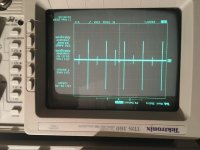
I have a 4 channel 100MHz digital scope, and a 100MHz function generator. My function generator, can provide a sweep frequency, and FM modulation signal up to 30MHz (I think). While in sweep frequency I can also trigger a square wave, with variable duty cycle on the Sync output.
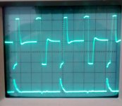
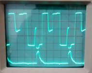
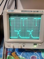
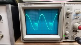
I wanted to tune the FM discriminator (S curve). To do this, I will have to generate a center frequency of 10.7MHz, with a span of 75KHz ... right ? But where do I inject it ? on the 75ohm aerial input ? and with what amplitude ? (the minimum for my function generator is 2mVpp). On the scope side, do I have to put it in X-Y mode, with the Y channel connected to TP4 ? ... but, shouldn't I have to connect a ramp signal on the X channel ? (I can only have a square wave, not ramp signal/sawtooth signal, coming from my function generator).
As for the MW part of the receiver, well, I think I'll need to replace the IC201 (LA1245), as I have signal coming in pin 3 ... "something" getting out of pin 7, passing trough the passband filter T203, and going inside pin 9, but nothing coming out of pin 13. But, I'm not too worry about this, as where I live, there aren't any stations to be received on this band. Maybe later, I'll take care of that.
Can anyone help with the tuning of the FM discriminator ? and what can I do about the offset on the tuning frequency ? Any help is truly appreciated
😀
Link with schematic and alignment tables:
files
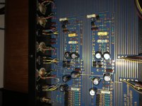
NOTE: On the schematic, I circled at green the components I have changed and at red is show the actual place of L8. And on the board silkscreen, there is also a mismatch between L7 and L8, but for circuit sake, just consider the placement of L8 show in red


