Philips CD610 disc spins backwards

Hi there

New on the table today is a Philips CD610 CDM-4/19.

Lens cleaned, disc spins jerky backwards when inserted - fraction of a revolution. Not reading TOC of a factory CD, shows ERROR in display.

Had it apart, cleaned all the connectors on the PCB, back together and same thing.
From the side a laser can be observed. The laser head is bobbing up and down.

It's late at night here so I've not been over it with an oscilloscope or DMM yet.

I've got the SM in English, just wondering if there's anything I'm missing?

I've also had a peek at the solder joints and can't see anything outstandingly bad. Nothing observed abnormal.

In the last week I've recapped an older CD460 successfully, also rolling op-amps too.
I noted that none of the electrolytic capacitors were off-value or with a high ESR, so I'm erring on the cautious side and not thinking it's them, as it's a newer model by 5 years or so.

Anyhoo...any pointers would be welcomed!

Cheers

GB

Hello from Amsterdam, Netherlands

Hi there,


I am a software developer living in Amsterdam since 2014. Originally from Argentina. I also lived in Madrid, Spain for a long time.

I have some experience with digital and analog electronics, and lately have been busy with a few audio-related projects. I actually registered in diyAudio more than 6 years ago but never posted. Better late than never!:snail:

I am in the process of building a class A amp, and if I can get a pair of those Jensen transformers, it's going to be based on Nelson Pass' F6 design.

Regards,
Iván

Is this design correct?

First, I would like to thank the members of the forum. I have benefited a lot from them. This is the first design I will make and I want to know whether everything is fine in my project or there are notes on it.
Project components
Drive ...
Peerless by Tymphany 835017 12 "Aluminum Cone XXLS Subwoofer
Amplifier ...
Dayton Audio SPA250DSP 250W Subwoofer Plate Amplifier with DSP
Tube ...
Precision Port 4 "Flared Speaker Cabinet Port Tube Kit
Bassbox Pro was developed In the attachment case pictures....
p_1593o7iwy1.jpg
[/url][/IMG]
p_1593whft02.jpg
[/url][/IMG]
p_159367bvr3.jpg
[/url][/IMG]

First Subwoofer - What should I pay attention to?

Dear DIY Audio,

I am thinking about building my first subwoofer this year, and I don't know where to start.

I was wondering what the are most important factors to pay attention to. So far I believe I have to consider:

1. It will be in an apartment bedroom (not too loud, not too big, wall to wall carpet)
2. Should I design it to be placed in the corner like a REL subwoofer to take advantage of the long axis of the room?

What other parameters or considerations should I worry about? What shouldn't I worry about?

I am nervous and excited to start! I'm a couple years out of engineering school (EE) but I haven't touched this space before, so any help would be appreciated!

Thank you so much!

Voltage regulator (LM317, LM7805) decoupling capacitors

I'm "refreshing" an Adcom GDA-600 DAC and would like some tips on the PSU section. The unit is now 27 years old and I'll be replacing the caps in the power supply.
I'll be using Panasonic FC for the main filter caps.

The decoupling capacitors for the voltage regulators used here are Nichicon VX (standard) 10uF 35V and 0.1uF MLCC (not sure which type) for the LM317 and LM337 adjustment pins.

Most of the components in this unit look to be very solid choices but in this case it does seem to be economic as these caps are used throughout for various duties.

I've read through many LM7805 and LM317 datasheets but since some are 40 years old, perhaps with changes in capacitor technology and availability, better choices can be made.

The schematic is attached with capacitors marked.
Red -- output decoupling caps
Green -- input decoupling caps for the regulators that are used by the PCM63-P DAC chip
Blue -- 0.1uF MLCC for the adjustment pins. (datasheets recommend 10uF-20uF here)

I would appreciate recommendations for each of these positions. As of now, I only chose 10uF solid tantalum for the output caps based on their usage in previous projects with the LM7805.

P.S. I'm replacing the LM317/LM337 with LT317AT/LT337AT which have slightly better specs.

Attachments

  • GDA600 PSU.PNG
    GDA600 PSU.PNG
    119.7 KB · Views: 630

DIY line output transformer

Lately i am experimenting with various diy opts for use as line output transformers intented to be driven by trioded pentodes with Rp from 2k to 5k. My target is something around 5:1 and the best banwidth possible. I am able to wind any type and got alot of time and experience. I have tried so far 2p-2s 3p-3s and also split bobin 1p-2s + 1p-2s and 3p-3s+3p-3s. All of these with no luck yet as resonances seem to fall inside the audio band or near it. Mostly i use around 3000 to 4500 primaries with paper interlayer insulation and sized EI75 and EI84 grain oriented cores. Any help would be appreciated.

Hello from Spain

I'm Pedro from Madrid.

I have interests in DIY electronics solid state, like JLH and and MOSFET amplifiers, and digital sound projects.

I'm a modest builder, though I'm now working in a music-box with Raspberry 3B+, for now it has a big linear power supply, a cheap chinese DAC (PCM5122 based), infrared remote control, and USB external ports, and auxiliary USB for powering external hardisks and external DVD.

My next step is add a cheap 3,5" color LCD screen, a wheel controller and set of buttons to control it.

Later I have plans to buy a cheap USB radio to add DAB tuner.

I'm waiting for heatsinks and several kits to build a JLH amplifier.I have already made a little linear power supply for JLH1969 with 27 V dual rail and 2,5 A.

Hello This is Chris

Hi
My Name is Chris and I'm a long time member of this forum..
I'm living in BERN, Capital City of Switzerland.
Bad as it is, I was just reading here once a while. and this since 2012 the day I registered here.

DIYAudio kept my username secure and I my password..
If there wouldn't be a person who asked me if I would place some of my Builds here, I might wouldn't write this here today.

Now, since I gave my promise to that person, I will keep my promise.
I started building Amps back in 1974 *I was 22 that time*, so this shows you my Age, which is about the same age the person who asked me.. I will not name this person but the person is also a senior member here.

Myself, studied Car Engine Engineer in Swiss from 1968 - 1972.
Have seen Jime Hendrix live in Concert, Led Zeppelin, Clapton, Deep Purple, Pink Floyd, Roger Waters and many other Groups in that time and also in the last 18 Years.

Moved to Asia in 1974 till 2002, when I returned to swiss inclusive my Family..

As I couldn't work on my profession in Asia, I ordered some Electronics Books from Switzerland and read them at least ten times. I was very eager to learn that stuff.. But I was young and travelling all throughout Asia, just working when I needed Money to support me living expenses.. In 1990 I met my Wife, and then we seddled down in Bangkok. In the meantime I learned to read write speak Thai, almost as good as a Thai..

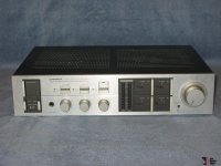
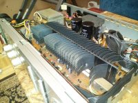
1975 I build my first Amplifier * Pictures will follow soon* it was an Kit Amp Class AB 100 WATT this amp still works until today,.

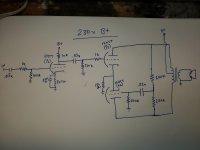
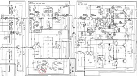
1976 I found myself digging very deep into Amplifiers but in fact I didn't had a big clue yet, so I started to read Electronics booklets in english and Thai to get more knowledge..there it was that I found a schematic of a Class A Amplfier which Input device was a UA 741 * one of the worst IC's * which is still sold till today..

This was three stage Amp as predriver was a SB649 * Hitachi* may one of the best Low Voltage transistors that time *UCE = 160V Imax 3Amp and Ptot 3 Watts. Then Drive was a SD669 this is complimetary to SB649..
Output were two SC1047. No current source, but instead they used a 220 Ohm 10Watt Resistor with a 2200 UF 50 volts cpapcitor to get the Current working while crossing by a Reversed diode between the output Transistors.

So I build that amplifier and believe me I gave my best but this Cirquit never worked as it was supposed too.

So after a few weeks I managed to get it working, removing the 220 Ohm Resistor with another SC1047 as Current Source and removed that Capacitor as well.

Exchanged this diode with a HIGSPEED Diode and later with a SB817 which is the comlimentary Transistor to SC1047. That time I had only a Sanwa Analog Multimeter, no Scope nothing. But I got that too work and with a decent sound. I did build that in the early 90'ies again and went to get a computer read out it was quit good, but in the meantime I owned a Hameg Osciloscope 20 MHZ. I also will place that here.

Since then I always tried to build Class A Amplifiers, also owned a Threshold second hand, and still Own a Forte Audio A 100, couldnt afford a new one used them with Marantz Speakers Model HD880. These were American Made Marantz 4 way. Beautiful sound.

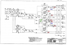
2002 We returned to Swiss, so I couldn't move all my sound Equippment to Swiss. Now I started over again to build Amps. Then I saw a Class a Cirquit of a Australien guy Named Scott Elliot, he is the counterpart to Nelson Pass.. Bot of them are Geniuses when it comes to Amplifiers..(Check out that Picture below or use the link.)

Anyway he created a Amp called DOZ * as he told me * this was the Amp he fought the ZEN amp of Nelson Pass. The meaning of DoZ is = Death of Zen.

Here you will find a link to this Amplifier..

Death of Zen - A new Class-A power amp

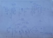
I also build this amplifier but before I build it, I modified the Schematic to dual Rail Voltages meaning +- Rail with commone Ground.Also meaning rearranging almost the whole cirquit.

Changed Transistors to MJL4281

Added a Servo Control and again removed any pieces in my sight not needed. Like a couple capacitors. Added a Transistor between Input and Drive. and several other things. then when it was finished I send a mail to Scott and showed him the work. and when I talk about work, then I mean all of it. No Secrets kepts. This amp * the modified version * which is quite different from the original works fantastic. I build 7 Version of this one, latest was in 2017 and has only the Input Section which still shows the Tremendous knowledge of Scott Elliot in designing Amps..

For Scott and also Pass, these two guys are unsurpassed and are the " Gurus" = MASTERS of Amplifiers, when it comes to Amp developement. Here my thanks to both of them for their absolut best work there is out there.

If in any of the upcoming Artwork, Schematics is others People Work is included then it will be notified and the credit goes to owner.. Even the Amp design was made by my, the IDEA is the groundlayer for this and this should be in any way and Matter given to its owner..
By the way: I building amps for FUN not for a living.

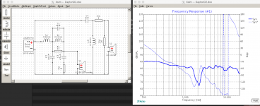
This Year I created a few different Schematics of Class A. Things which actually shouldn't work but they do work..

I will place schematics, Spice Work, Layouts and the build up of every Amp I created or Modified. I do not copy paste Amps. But may taking advantage of the Idea of these two Masters they had in the past, and would fit my thoughts of Amps. there is barly enough to get your own design.. there are only three ways to create an AMP..

Thanks

Regards Chris Hess

Anything inherently wrong with this design?

I have cobbled together and modified a few headphone amp designs that I found on the internet to utilize parts that I have on hand. I have built a working single-channel prototype and it seems to work well with an extreme amount of gain into my cheapo standard impedance headphones. I was hoping that someone a bit more well versed in tube amp theory could tell me if anything is inherently wrong here. My goal was to create a cheap but functional design. Total bill of materials not including an enclosure should be ~$100. B+ is 230vdc but I still get an acceptable amount of gain at 120v through a regular isolation transformer. I didn't change any component values for the lower voltage. I just changed power supplies. The output transformer is a Dukane line matching transformer. Primary~15k to an 8 ohm secondary. This isn't specifically what it is designed for but they cost $4 each and are rated to 4 watts. The sound isn't too shabby either. The design would use three 12at7 tubes. 12au7s also work, but have less gain. Still way more than necessary at the 230v B+ though. I haven't tried any other tubes in it. Power supply is just a typical transformer/ bridge rectifier/ pi filter setup.

Anyway, sorry for the crudity of my lovely artwork and I appreciate the help.

Attachments

  • 20200426_203359.jpg
    20200426_203359.jpg
    573.8 KB · Views: 485

Compression driver with a highest sensitivity available

Hi guys

Please advise on the matter as in the title. I am looking for a compression driver + horn combination with a sensitivity of at least 110dB, but in the 2-15 kHz band. At frequencies close to the lower limit, the sensitivity may be arbitrarily higher, but it is important that it does not fall below 110 dB in the entire indicated band. I deliberately wrote sensitivity - nominal impedance is irrelevant, and a low value increases the sensitivity. Impedance at the level of 4 Ohms would solve this problem and many currently available models would meet the indicated condition - the problem is that they are not available in the 4 Ohm version...Of course I'm looking for a hi-fi/hi-end driver, not a fire sirens ;-).
Thanks in advance.

Pearl layout - how to organise things to avoid noise

I'm drawing a new layout for pearl because I have some slightly different parts and I enjoy the process of reading a schematic, make the layout and etch it my self.
But since I am redoing it completely, I am trying to figure out if I should change the layout slightly.

The input section is according to the article and threads very sensitive to noise. If the two boards are in the same case, the input of one of the channels will be very close to the output and voltage regulater of the other - is that a problem? Would it be a good idea mirror the channels so the two input sections can be together or far apart?

I'm making it for someone I know and I think he will prefer, if he doesn't have to split two many cables, so Right and Left should be placed close to each other for input and output if possible.

I have made some suggestions and attached primitive sketches. What do you guys think, should I try something new or try to get as close as possible to Waynes layout?

Attachments

  • pearlcase.png
    pearlcase.png
    5.9 KB · Views: 2,746

  • Locked
Bose 901 II reproduction... the right way

I know nothing about putting speakers together. This is my first time. Thanks for understanding my incorrect use of terminology and stupid ideas.

I have fallen in love with the Bose 901 II design aesthetic. I would like to build my own but with a more conventional driver setup. I think I like the idea of 89% of the sound coming from the back, and 11% coming from the front since I can only afford cheap drivers. This ratio doesn’t need to be perfect.

How would you setup speakers to do something like that? I assume you would do a combination of sub/mid/tweeter. Which go on front and which on back keeping in mind the back has 2 panels and should be balanced.

I don’t know that I need specific driver recommendations at this point (but happy to hear them). I’m just looking for direction and what to look for.

Bluenote Koala No Power

Hi, i currently have a bluenote koala cd player. When i plugged it, ther eis no power to the device but there is a whining noise coming from the power supply/cd drive area. On closer inspection, one of the capacitor on the power supply is bulging. Do anyone know what is the cause of the problem? Or do anyone have the service manual for the bluenote koala? Thanks!

A tube amp for an odd beast

Hello and thank you for stopping by. I need to throw this out there, and start getingt to it.

I'm gearing up for my 3rd tube amp build, but, this one may stand to be something different from my previous builds - I've built a Fender 40 watt and a 20 watt 6V6 Marshall plexi. I'm an electronic technician pretty much by trade so fortunately, these builds went well and I use the Fender as my gigging amp.

I need to build a third amp for an instrument I made. On first sight, this intrument looks like a walnut Stratocaster with elaborate brass inlays and one single pickup, a humbucker in the neck position. This "guitar" will never be picked, plucked nor strummed. It is a fretless that I made strictly for use with an ebow (electronic bow). It is a pure, singing melody instrument who's lyrical expression is far close to a cello or violin than any guitar you would ever hear. It is my big, 10 pound electric violin/cello that looks oddly like a Fender Stratocaster. Primarily I've been using it straight through my DI - micpreamps - stereo FX processor - D/A converter into recording software. I'm fairly convinced that it would benifit from an amp that has a strong Hi Fi element(s) to it. It can sound good through a typical clean guitar tube amp but sounds a bit strident or mushy. a little of that is OK but it lacks a more pristine quality that is heard though my relatively hi-end home studio front end.

I'd like to use a pair of KT88's for the power section. The idea of having good headroom at moderate stage volume is attractive, and plus, I just like something about those tubes, even the way they look.
The option for UL also is something that interest me for this project. and if for some reason, I preferred straight pentode, I'd still have the option.
I build a "tube designed station" out of an old Bogner amp so, I'm in a good place to try different topologies as I go.

Strangly enough, this "guitar" used with the Ebow, volume pot full up yields an output of nearly 3 volts at maximum. This is just about line level and a very high output compared to the typical 250mV of a typical electric guitar. So right there, It would be easy to push every stage of a typical guitar tube amp into saturation (which is the opposite of what this will need).

In my recent looking around for alternatives I found those Dynaco Hi Fi amps interesting, that perhaps they may be a good start to hear what this strange instrument would sound like though a more Hi Fi tube amp.
What would your first inclination be for an instrument with 15k ohm @ 2-3volt output be if you wanted it big, rich and clean?
I figured it wouldn't be too much to ask for 60-70 watts from a pair of KT88's in UL.
Thanks muchly for your time,
Phil D

Help for PCM1704 Delay Circuits and Other

I try to make a NOS balanced dac with 4xPCM1704 and JLSound I2SOver module.Before to draw layout and PCB boards i need help and some advice from members if it possible.My circuit like that block diagram.My questions are ;

  1. Do i have to add a delay data half clock cycle circuit after my buffer and 7 bit delay like DDDAC ? It confused me.
  2. Do i need to use a SRC4192 after WM8804? Or my diagram is enough to get coax and optical inputs?
  3. According to members experience, NOS or DF1706 Oversampling.Which one should I prefer?
Best Regards

Attachments

  • DAC.png
    DAC.png
    139.2 KB · Views: 319
  • DAC.pdf
    DAC.pdf
    571.6 KB · Views: 100
  • DAC1704 Circuit.png
    DAC1704 Circuit.png
    69.2 KB · Views: 343
  • dddac.png
    dddac.png
    30.4 KB · Views: 320
  • DAC1704circuit.pdf
    DAC1704circuit.pdf
    844.6 KB · Views: 123

Missing PCB pad.

Just replacing some damaged caps in an Audiolab 8200CDQ. This is the second time this has been done as I have power supply issues where I live. The first recap was done by an IAG certified tech. When I unsoldered the caps I noticed to of the pads on the underside of the board are missing. They are intact on the surface. Can I still solder to these? Just use more solder so it runs through the bottom to the surface pads? What’re your thoughts?

Attachments

  • 17221376-012A-4CCC-AC75-8D9F81180994.jpg
    17221376-012A-4CCC-AC75-8D9F81180994.jpg
    613.2 KB · Views: 168

Stromberg Carlson ASP-60 out of phase transformers

Can someone explain to me the reason for this stereo amplifier to wire the output transformers out of phase from each other? The primaries are flipped from each other and the feedback windings are also flipped from each other but the speaker taps are wired in phase so the outputs are essentially out of phase from each other if you hook up your speakers correctly. I don't believe it's a drawing error since there's an amp on eBay that someone wrote a warning on the bottom plate about its reverse phase so it is wired correctly according to schematic. Very strange. This is also the second half of an integrated amp (full pdf schematic) section but can be used independently. But in the preamp section there's no phase switching on either channel. Head scratching.... 😕 :scratch2:

Any thoughts?

Attachments

  • Stromberg_ASP-60_schem_1600X2600.jpg
    Stromberg_ASP-60_schem_1600X2600.jpg
    472.8 KB · Views: 238

Is it ok to have metal parts close to esl diaphragm?

Hi,

I started a new (fourth) ESL DIY project last winter. This will be the first one that has an integrated damping screen. I glued the damping screen on the wooden frame (which holds the stator wires), and on top of the screen I put the pvc spacers. The glue penetrates through the damping screen (mesh) and this bonds to the pvc spacers laying on top of the damping screen.

It seems that the damping screen is glued well to the wood, but the pvc spacers are a little loose. This is not a big problem as both stators (front and rear) will be bolted together, but I want the pvc spacers to be firmly attached to the frame. So I came up with the idea of using screws to attach the pvc spacers to the wooden frame (with the damping screen in between). I would think this is ok as there is no electrical connection between the screws and the diaphragm: the screws will lay a little lower "in" the pvc spacers and I will only apply conductive coating on the moving parts of the diaphragm (not where it overlaps the pvc spacers). I will use a small copper tape to connect to the bias power supply, but this won't overlap / touch the screws (and bolts) either. As in previous models there were not probems using bolts going through the stators and pvc spacers, I would think it is ok to use these extra screws to attach the spacers to the wooden frame?

I hope I explained my situation clearly enough...

Offset 20mv Hiraga PrePre

Years ago I bought a Hiraga PrePre from 404 Not Found

I've used it before and was able to zero the offset. However, this time I am using a battery bank (to charge phones) and the voltage is 5.18VDC. When powered up I cant get the offset lower than about 20mv. Would this fry my coils of my Denon DL103 cartridge?

Any tips how to get a lower mv? Do I need to install a different pot or could I do it a different way? I have also noticed that the offset voltage goes up when I remove the battery bank. Is this normal? (voltage might go up to several volts)

Rear fill speakers and signal done the right way

I have now gotten my hands on a Helix p-DSP cheaply and a SPL-Dynamics ice-150.4 amp for my front speakers. I plan on making my Alpine SPR-50c speakers active. I have a kicker DX125.2 laying around and have planned on adding rear speakers.

Now I have heard from all the audiophiles to not bother with rear speakers, but I found the right way to do it. Now I don't know how to implement it.

First the rears should be band-pass eq:ed from +-200hz to +-7khz and 20+ms of delay should be added. Then the right signal should be added out of phase to the left signal and vise versa. This should make it so that they don't play any centered sounds like vocals, that exist in both L and R signals. This is pretty much what the early Dolby Pro Logic processing did.

The problem is, how do I do this. Only the newer Helix DSP processors seem to have this function in the input mixer. And the other way is to use balanced signals and just cross the signal wires. But I don't have either, to my knowledge.

Would there be an easy way to implement something like this? And if so, should I use coaxials or midbass speakers in my rear deck?

Ground Zero GZRA 1.1650D class D IC to recognize ?!?

Hello again guys !

Ground Zero GZRA 1.1650D - blown output, no gate drive even if a feed a strong RCA signal.

Voltages are OK at pads. PS section is OKAY.

Have to change to IC-U509, as this one gives out the gate drive directly to IRFB4227 - but it's scratched. This is the first time i ever see this chip used in class D.
U 108 is 74HC02D.

Can anybody give a clue ?

Pictures attached.

Attachments

  • 0.jpg
    0.jpg
    319.3 KB · Views: 217
  • 1.jpg
    1.jpg
    368.8 KB · Views: 236
  • 2.jpg
    2.jpg
    379.2 KB · Views: 203
  • 3.jpg
    3.jpg
    375.8 KB · Views: 237

Power Supply switching frequency - what?

I greet all the members of the forum.
I apologize if maybe I posted in the wrong section, but in fact, the purpose is to fix a power supply of a car audio amplifier, so it seems right.
I'd like to understand one thing.
When we speak of "oscillating frequency of a switching power supply" do we speak of the frequency that is read on the gate of the mosfets, or of the triangular one (sawtooth) present on pin 5 of the TL494 or pin 6 of SG2525?

POLK LS-70 mods

Hey gang,

I recently picked up a set of these for a friend looking to upgrade from his small B&W standmounts on the cheap.

http://www.hifi-classic.net/review/polk-audio-ls-70-118.html

I was able to fix a voice coil rubbing issue by turning the offending driver around 180, worked like a charm, however I noticed on doing so that there was no stuffing behind the driver?
This is kind of a 2.5 way design? The driver I removed was just below the tweeter, plenty of stuffing between it and the lower woofer but none behind it?
I might try some foam I have around but I'm curious to know if this omission had a reason behind it? (pun intended)

Old 80's Panasonic Boombox

I picked this up a few days ago: PanasonicBoombox.jpg - Google Drive

It's a Panasonic RX 5085. Sounds surprisingly decent, maybe a little light on bass, but I don't mind. Contrary to my username, I don't know anything about these boxes. 🙂 I did have a few questions though, so enlighten me.

1. How does the "ambiance" mode on this thing actually work? There's mono, stereo, and ambiance. Flipping it to that mode seems to artificially expand the sound stage and create this fake "surround sound" effect. I don't really like it because it makes the music sound weird, but I am curious, how does it actually modify the signal to achieve this effect?

2. What type of enclosure do the drivers sit in? From what I could tell, there's no ports, but the design looks too leaky to be a sealed enclosure. Does this mean it's open baffle like most car speakers?

3. I was planning to open and clean everything up inside. Will adding a bit of polyfill or other dampening material inside the enclosure improve sound quality and bass extension? Or will this cause other problems I'm not aware of?

4. Do these boomboxes have the same issue with the worn foam surrounds as bookshelf speakers at the time? Will I have to replace the surrounds soon? Or are they rubber or something like most of the modern stuff?

Orion Hcca 5000 ESP indicator “On”

Hi.

I am working with an orion hcca 5000. it is the first time that I work with this brand and the ESP protection system. This amplifier when connecting remotely, only lights the POWER led and 3 pulses the ESP led and remains fixed. there is no consumption at startup. There is no source pulse when connecting remotely, nor does it raise the rail voltage. Can someone guide me?

Attachments

  • WhatsApp Video 2020-05-21 at 20.38.18.mp4
    704.4 KB

MJL4281/MJL4302 or MJL21193/MJL21194

So what is the preferred choice of the 2?

So far I think the MJL4281/MJL4302 have more linear gain and can have higher voltages.

On the other side the MJL21193/MJL21194 have higher SOA ratings. The temp derating is also lower.
They are slower also.

Looking at the data the MJL4281/MJL4302 looks more refined/faster/less distortion as apposed to the MJL21193/MJL21194 which are more robust.

So what are the experiences?

I've got this Amplifier PCB board based on the lme49810 quite cheap.
It uses 3 pairs of 2SC5200/2SA1943 but I don't know if these devices are legit.
So I was thinking of replacing them and could use something better as well.
These are 30Mhz devices so the MJL4281/MJL4302 are not that much faster. (35Mhz)
The gain will be better for the MJL4281/MJL4302 as fas as I can see. This is a good thing as the LME49810 has to deliver less current.
I was thinking for voltage rails of around 70v and driving 8 or 4 ohms


MJL21193/MJL21194 will give more SOA reserve but are slower.....and lower gain.

So would be nice to hear some experiences.

Headphones extender cable?

I find my self not using my headphones very often. I have built both Whammy and Starving Student II. I think the reason is that I can't sit in my normal listening position. The headphone cable is rather short so have to stand or sit on floor close to amp. Do you all use 4-5m extender cables to be able to sit in same position as when listening to the speakers?


If headphone is like say 32 ohm then a few mOhm of the cable impedance should not influence on sound quality?


I could probably use rather cheap cable to make a DIY extender cable?

How to wire dual preamp (linestage) outputs ???

Hello..

I'm building a linestage and it will have 2 pairs of RCA outputs.
Should I just connect them in parallel?
Or is there something more I should do?

Is some active circuitry needed?
The linestage is itself a tube buffer..... (with reasonable output impedance)

The purpose/usage will be situations like driving a main amp along with a subwoofer amp, perhaps with only one powered some of the time...
and having a headphone amp connected as well as a main/speaker amp, but naturally only one powered...

I realize that the input impedance the linestage will "see" divides between the 2 amps.
Divide the sum of the 2 amps' input impedance by 2?
Did I say that right? I'm really tired right now.. sorry....

Thanks in advance!

Greg

USB to SPDIF IC recommendations?

I'm looking for an IC to provide a USB to SPDIF interface. Basically, the cheapest hardware configurable device that can do 24-bit at 48Khz. Some examples that are close, but not exact would be:

CM108B (i think it's limited to 16-bit, let me know if i'm wrong)
PCM290x (also limted to 16-bits)

TE7022L seems to be good fit, but I can't find it in production / for sale anywhere. Leads?

Any suggestions/recommendations would be appreciated as I've spent some time looking and keep hitting dead-ends with this.

12"+???+STH-100 Horn

Hello Wise DIYers,

I'm creating a stand mount speaker pretty similar in nature to the Troels Gravesen Faital 3WC Faital-3WC.

However I would like to use the Faital STH-100 horn and compression driver which I have spare already. The system will be fully active with time delays and FIR processing.

The question I ask of you is should I go for a 6" or 8" midwoofer(or something else)? I would like to cross to the STH Horn at around 1.6KHz or above and not more than 300Hz to the 12".

Any advice or suggestions gratefully received.

Alex

A WE-91B project

Hi guys, a friend ask me to make a valve amp for him, I want to use WE-91B, since his speaker is TAD2402(sensitivity:93dB). He want to use 300B, so I think WE-91B is a good choice
1.jpg

this is the circuit I draw in Altium Designer, because I want to make it into PCB
2.JPG
some of the components has been set to 91B accroding the original schematic

It is impossible for to collect the original WE components to make this amp, so I deceided to use morden components to make it.

DIY Phono Stage Recommendation

Hi All,

Does anyone have recommendations for a diy phono stage kit? I think I want to prioritize a really low noise floor. Other attributes are important, but after experiencing a Klyne phono stage and it's noise floor (or lack thereof) I think that falls in line first.

I've checked out the glassware kits, but I don't know the differences and advantages of the tetra vs. the aikido?

As well, the Pass Pearl 2 DIY looks really interesting but I just discovered that it can be used as an MC stage by adjusting the gain. In that you can use it for moving coils, I'm wondering if the noise floor is affected by increasing the gain?

Thanks for any future suggestions.

RS28F-RS180P-B80 as Hole Filler 3-way

I have been planning these for a long time and parts have been collected and ready to build. I finally took the plunge (pun intended) and used a router today to cut the driver cutouts with rebates with a circle jig. That's a lot of work to cut a couple of holes.

The speaker will be my new reference bookshelf (standmount) monitors using Dayton RS28F-4 silk domes and RS180P-8 paper woofer. I will use a second order XO with both drivers in positive absolute phase. A deep notch will result at XO frequency, so I will use the B&O Hole Filler technique to place a wideband midrange at the notch. The mid will be the very capable Visaton B80 with a first order filter on both sides that will perfectly fill in the notch (or hole). With proper offsets and crossover design, a flat phase transient perfect speaker should be possible.

The enclosure consists of a 0.56 cubic ft Denovo flat pack cabinet which will house the woofer and mid. The mid will have a sealed Dagger rear chamber for low coloration. I am still debating whether or not to make the woofer sealed or vented. The tweeter will be placed on a small trapezoidal baffle that sits atop of the main cabinet to allow setback for time alignment.

Sensitivity of system will be dictated by woofer and baffle step. RS180P-8 is spec'd at 89dB. Assuming circa -4dB baffle step loss overall system sensitivity will be 85dB. This matches the B80 almost perfectly and the RS28 will have to be attenuated quite a bit.

Initial simulations show bass extension around 55Hz to 62Hz depending on tuning. Bass won't be this speaker's strong suit but rather detailed mid range and clear resolved highs with excellent transient response will be the goal.

Some pictures of drivers after cutting out holes. Still need to make trapezoidal mount for tweeter. Then make measurements, then develop crossover in PCD or xsim. Lots of work ahead.

What's interesting is that the B80 has the exact same cutout diameter as the RS28. Is there any advantage to a MTW vs a TWM for an application like this?

The MTW gives the cool option of running this as traditional 2 way by flipping polarity of tweeter and not using mid.

571428d1474842256-rs28f-rs180p-b80-hole-filler-3-way-img_5260.jpg


Edit: I am going with tweeter mounted in main box with a waveguide to provide best vertical and horizontal polar response.

573055d1475723092-rs28f-rs180p-b80-hole-filler-3-way-boxes-rs28f-rs180p-b80-glued.jpg


WG-300 fitted to RS28F using 3d printed adapter plate:

573069d1475732224-rs28f-rs180p-b80-hole-filler-3-way-rs28f-wg300-adapter-assembled-2.jpg


573070d1475732224-rs28f-rs180p-b80-hole-filler-3-way-rs28f-wg300-adapter-assembled-3.jpg

Attachments

  • IMG_5260.JPG
    IMG_5260.JPG
    113.6 KB · Views: 4,134

Pioneer SA-1040 Amplifier : RESISTOR (R592 - .33X2/5W) Making Smoke and getting super

Resistor Getting Super HOT with some SMOKE! HELP PLEASE!

So i just changed the fuse 3.15 amp to my amp and since then the front lights are very dimmed (seems like low in voltage) and the big white resister (R-592 (right channel, please see the attachments, there are 2 big white colored resistors for each channel) is getting super hot and i can see some white smoke coming from the resistor and had to turn off within 1 or 2 seconds before it blows up or cause other damage.

It's not even clicking (the speaker protection relay), coffeehouse there is something wrong with some component. what seems to be the problem ? Some expert help please.

Attachments

  • SA-1040 Connection.pdf
    SA-1040 Connection.pdf
    677.7 KB · Views: 94
  • 1930062-caaaa14a-1983-pioneer-silver-face-sa1040-stereo-int-amp-amp-tx940-am-fm-tuner-100-wattsc.jpg
    1930062-caaaa14a-1983-pioneer-silver-face-sa1040-stereo-int-amp-amp-tx940-am-fm-tuner-100-wattsc.jpg
    134.2 KB · Views: 216
  • 11.jpg
    11.jpg
    184.5 KB · Views: 643
  • 22.jpg
    22.jpg
    110.4 KB · Views: 227
  • 33.jpg
    33.jpg
    190 KB · Views: 474
  • 44.jpg
    44.jpg
    158.8 KB · Views: 249

Novice trying to repair a Pro-Ject Tub Box S2

When I turn on my hi-fi and play an LP the the right channel plays for about 4 to 5 minutes and then goes silent. All other components work. I assume the two Ecc82 vacuum tubes have Left and Right circuitry and the left tube is overheating. If my assumption is correct the fix should be replacing the tube on the right. Or I could replace both tubes. Does any one have a suggestion?

The Analogue Addicts Phono Preamplifier 2006 Edition

Konnichiwa,

First a little history.

The original "Analogue Addicts Phono Preamp" may very well be the most popular Phono Stage design on the net, it is certainly talked about and referenced a massive lot. I have seen this cropping up in all sorts of unlikely places.

Originally the design was posted to the UK based "Analogue Addicts" E-Mail list in either 1996 or early 1997, as response to moans that there where no simple phono stages for DIY and nothing affordable and semi-decent to buy.

In the last 10 Years Vinyl has taken a resurgence few would have predicted. In this day and age you cannot throw a brick or swing a cat at a HiFi show without hitting a few Phonostages, from the sub $ 100 NAD PP1 to the sub $ 30,000 Boulder 2008.

Still with all these riches many DIY'ers talk about my little "semi budget" gem from the mid 90's. A republication of a later re-write in article form is found on my (long not updated) website:

The Analog Addicts Phono Preamp

I have of course moved on from this design, nice as it is. However, due to some current commercial work I decided I needed to "roll back" my system into something that is a lot more like commercial mid-priced High End (< $ 20,000 single source system).

I have build a speaker for that Job that pulls together what I liked best in technical terms about the SLS S8R Monitor, the Dynaudio BM15 Studio Monitor and the Sonus Faber Extrema.

I also wanted an "average" Phonostage, now I might be doing the AA Phono a disservice by calling it average, but in many ways it a simple, workman like design, with decent sonics.

Digging around in my fundus of stuff saved for future projects, samples, leftover parts from modification work and so on I had all I needed.

I'll list details about the practical implementation in another e-mail (it is likely quite interesting), short and sweet, while working up a list of the parts I did not readily have (mainly resistors) to pick them up from the local Maplin (sorta like Radioshack UK) I got to think if I had learned anything since the original AA Phono that could be easily applied.

In addition I wanted a simple AC powered solution and I wanted to pick up on some comments that have rolled in since and various discussions and debates since.

So (drumroll), may I introduce to the genteele reader

"THE ANALOGUE ADDICTS PHONO STAGE 2006 EDITION"

Here the signal circuit schematic:

An externally hosted image should be here but it was not working when we last tested it.


To go with this the powersupply:

An externally hosted image should be here but it was not working when we last tested it.


I'll discuss the differences and my implementation more detail later.

For the case I used once salvaged from an ancient, but very well build Hayes modem like this:

An externally hosted image should be here but it was not working when we last tested it.


The power supply is another IT Services throwout and once supplied a small HP Jinkjet Printer with 30V/400mA DC, I downgraded this unit to an AC only.

Finally, I have quite a number of Preamp Boards from the Shanling SP-80 Monoblocks which I tend to pull out like rotten teeth during mods. As these have space for four regulators, various rectifiers, capacitors and two Op-Amp's (with the PCB Patters alread offering an OPA627 option) and enough space and holes for the pre-pre section in the place that houses the PGA2311 volume control....

An externally hosted image should be here but it was not working when we last tested it.


An externally hosted image should be here but it was not working when we last tested it.


I'd show some photos of the implementation, but it's not overly neat.

I encountered one key problem, as originally the case was not screened (alu parts not connected to ground) the MC setting especially tented to pick up noise. I solved this by using screened wiring for the inputs and thereabouts and I also found a way to connect the Alu case sleeve to the screen. There is still some slight sensitivity to external hum fields, but it's now okay enough.

I fitted captive leadouts for the line out and jacks for the inputs. Parts quality is noted on the schematics.

More another day.

Sayonara

500 ohm output?

Hi! I have a Wurlitzer 1400 Jukebox which uses a 514 tube amplifier. In addition to driving the internal 8ohm speaker, there is also a two-screw terminal strip to allow connection of external speakers. This output is labeled “Aux Speakers 500 ohm Line”. There is also a “fader” rotary switch that the manual explains allows the output to be balanced between the internal and aux speakers. The manual explains that the aux speakers should use line transformers to convert from the 500ohms to the individual speaker impedance.

I know that there are constant voltage speakers that are typically rated at 25, 70.7, or 100 volts. But there is no reference in the manual to constant voltage or any of these voltage levels. Does the 500 ohms imply one of these voltages, or is the 500 ohm output something completely different? I can find a lot of info about constant voltage speakers, but no references to 500 ohm outputs.

Thanks for any help!
-Steve.

Potting transformers

I have seen many designs that show potted transformers and have often wondered if their is any sonic benefit to doing it or was it just to make a unit appear more pleasing to the wife/girlfriend. In any case can someone go thru the proper procedure for potting one's own transformers? What is used for potting material? Geez this is starting to sound like a gardening post. At any rate... any information will be appreciated as usual.

Thanks
Joe

Wayne J Dayton 2's crossover in Xsim

So a blast from the past here.. I had to use the wayback machine to get the schematic and writeup:
The Dayton II Project

The writeup specifically calls out using a 2nd order high pass and tweeter with positive polarity, vs testing with a 3rd order and inverted polarity. The thing is, when I model it, nothing seems quite 'right' which might be from drivers and spec data files changing with time? You can see in the attached images the original crossover, my Xsim version of it, and the poor results from the sim. Inverting the tweeter does improve things, but is also not great. (also pictured)

I can obviously tweak this to get different results, but the drivers I have ARE from many years ago and possibly different and better matching the measured results at the wayback link? Or did I make a mistake anyone can spot with the schematic in Xsim ?

Attachments

  • Screen Shot 2020-05-20 at 11.02.49 PM.png
    Screen Shot 2020-05-20 at 11.02.49 PM.png
    243 KB · Views: 124
  • d2xover.gif
    d2xover.gif
    31.1 KB · Views: 121
  • Screen Shot 2020-05-20 at 11.10.51 PM.png
    Screen Shot 2020-05-20 at 11.10.51 PM.png
    88.1 KB · Views: 111

FS: Nice front panel for RPI streamer

I have a nice front panel from FPE. It was made for use with a Raspberry PI based streamer.... unfortunately the cavity on the inside does not fit the VFD I am planning on using.

The panel is 4mm thick.
On the rear side, there is a cavity behind the "Pi" symbol for inserting a IR receiver if wanted.

The panel costs around $65, I will sell it as-is with the LCD and backpack inside for $25 shipped in the US.
It fits Hammond series 1455 cases, which come in varying depths that can fit a Pi project (see pictures for an example)

In my project I used a Digi+ and put a BNC on the rear panel, but you can use a DAC module and put 2 analog RCA's for a complete streamer.

P.S. There are 4 threaded holes on the inside for mounting the LCD. 2 diagonal ones have perfect alignment with standard LCD's, while 2 are offset and cannot be used. None of this really matters as the LCD fits snug in the cavity and does not actually need any screws at all for a secure fit

Attachments

  • 2020-05-20 16.35.20.jpg
    2020-05-20 16.35.20.jpg
    81.2 KB · Views: 307
  • 2020-05-20 16.35.01.jpg
    2020-05-20 16.35.01.jpg
    212 KB · Views: 323
  • 2020-05-20 16.35.48.jpg
    2020-05-20 16.35.48.jpg
    125.2 KB · Views: 307

How can i do v-cut and stam-hole in proteus ?

Hello everyone
I wanted to make pc to a factory in china but they send this messages and made me money refund.
How can i do v-cut and stam-hole in proteus ?
Best regards.

Attachments

  • Screenshot_20200502-121309_Chrome.jpg
    Screenshot_20200502-121309_Chrome.jpg
    340.2 KB · Views: 185
  • Screenshot_20200502-121300_Chrome.jpg
    Screenshot_20200502-121300_Chrome.jpg
    345.3 KB · Views: 194
  • Screenshot_20200502-121253_Chrome.jpg
    Screenshot_20200502-121253_Chrome.jpg
    333.8 KB · Views: 173

STM 32 F4 Discovery and Audioweaver, anyone tried?

Audio weaver supports the cheap STM32 F4 Discovery.
Audio Weaver® - the Only Cross-Platform Audio Design Platform | DSP Concepts
STM32F4DISCOVERY Discovery kit with STM32F407VG MCU - STMicroelectronics

Has anybody tried it out as crossover or FIR filter?

As mentioned in other post:
http://www.diyaudio.com/forums/digital-line-level/195791-open-source-dsp-xos-68.html#post4248409
You need extra ADC or SPDIF in as the card only has mems mic and I2S in.
But in principle one could make a very cheap FIR filter for bass correction or I2S digital 2 way crossover.
I guess with clever downsampling the 12-bit, 2.4 MSPS A/D converters also could be used for audiosignals with only a AFE added. (Especially for bass applications)
SR 2 400 000 Hz
n 10
SR/(2^n) 2343,75 Hz
So about 22 bits at 2k SR.

I know the audio weaver software is very powerful and has quite OK learning curve.

The STM32F407 is 32-bit ARM Cortex-M4F. The F meaning it has extended DSP instructions
http://www.dspconcepts.com/sites/default/files/white-papers/STM32Journal_DSPC.pdf

Regards Torgeir

Poindexter Musical Machine Build: power supply

I am new to builds but have begun the Poindexter 6v6 Musical Machine. Very basic question: How does one connect the Power supply to 2 audio channels?? The schematics show power supply connections to only one channel. Thanks so much for any help.

Attachments

  • Audio circuit 2006.jpg
    Audio circuit 2006.jpg
    49 KB · Views: 484
  • Power circuit 2006.jpg
    Power circuit 2006.jpg
    22.2 KB · Views: 476

PPI 2050AM doesn’t pass audio

Amp has good rails and +/-15v for the opamps is also good. Output stage has a few mv of offset, not objectionable. No output though. Probed around on the TL074 and LM833 hoping they were part of the preamp, but found no signal anywhere when the amp is fed a sine wave. Do these have mute circuits? If not, I’ll need a schematic to chase down where I’m losing the signal. Thanks in advance!

Enclosure design - Exactly what is required?

Hi all and preemptively thanks for all your help!

So I'm dipping my toe into the world of speaker design. I've ordered some books and got a few papers ready to read but in the background I was just hoping to ask some questions here to supplement.

I personally believe most things are easy when broken down into small chunks, I'm an engineer in the aerospace industry and while nobody knows everything about a whole engine, its too complicated, people learn to design small parts of a large assembly and you dont really need to know that much at all in the grand scheme of things.

So the first 'chunk' I wanted to delve into was the enclosure design, as being a mechanical engineer this is the bit I feel most comfortable with.

So my question is really, what is the list of requirements for a cabinet?

So my understanding is as follows:

  • High stiffness - which would be a material with a high Young's modulus and a structure with high 2nd moment of area (or something like that)
  • High damping - the speed in which vibrations in the structure decay in this instance.
  • Low internal reflectivity - which I think is to do with the ratio of acoustic impedances
  • The shape of enclosure itself - this seems to me where it gets difficult, the others are all relatively straightforward. I understand you dont want straight edges in order to remove internal reflections. But say if the nautilus shape is idea, why doesn't everyone use it?
  • Internal pressure - it would seem to me the ideal internal pressure (x area of the driver) would match the force required to overcome the resistive forces of the driver itself minus the force the driver can create itself. Or more realistically isobaric.

I haven't done any dynamics since university so I'm a bit rusty so sorry there's probably loads of mistakes in there.

Would people be able to list what they believe are the main requirements for an enclosure so I start evaluating the best compromises to make.

Class AB Amp Possibilities??

So I have built the Pass AB amp and am pleased with it. The problem is that I'm running maggies and can tell I need a little more power. Can I run a balanced signal +/- into the right and left of the amp input and pull my speaker output from the two positive outputs of the amp? Bridge them in this manner? If so I have other boards that I could build another unit and bridge it also. I understand the load issues that the amp will see and have to take that into consideration. Just thinking out loud.

Replacement Drivers for Height/Atmos

Hey guys. New poster here. Im trying to get some help with updating some old speakers on the cheap.

I know this is going to sound crazy but I think I need to replace my 4" drivers in my JBL n24's that Im using as height speakers. Yes, I said n24 LOL. I picked them many years ago thinking they would match fairly well with the tonality of my JBLS38's. These n24's are "breaking up" at volume which makes me think I need something to handle the power. If I run the same height signal to one of my mains, the sound does not distort. The n24 are only rated to 100 watts. Im thinking I need something better than 150 watts. I tried a speaker rated at 125 but still experienced the distortion. (less at the same receiver volume but still there). Can I get a 4" driver to bring the power rating up of these little speakers? This is a budget system so purchasing SVS, Klipsch, or other purpose made height speaker is not an option.

This is about the only one I could find in a higher wattage.

https://www.parts-express.com/morel-...-ohms--297-002

Thanks

SEAS tweeters Acoustic Energy AE1 Series 11

Not sure if I am in the right place for this! I have a pair of Acoustic Energy AE1 speakers fitted 25 TAFC/W-AE H 617 tweeters which are open circuit. I have carefully dismantled them but cannot see an obvious break in the wire.
Can you obtain replacement diaphragm/ coil assemblies ? Alternatively can they be repaired - if so can anyone in the uk help. If anyone has a pair of SH tweeters please let me know asking price!!

Trying to ID this capacitor

Hi all. Could I please get your help to identify this capacitor type (per attached photo)? I can't find this form factor on any of the color-code charts.

I'm assuming it's a high-voltage poly or maybe paper? It's one of several used as a decoupling cap in a little console tube amp from around 1960, built in Australia (I think). They are all the same color scheme with no other markings. Photo is of the one that looked cleanest!

A couple of these caps show cracks so I'll replace them all. I intend to measure them as I remove them, but any help to find a relevant chart to decode these guys would be appreciated in case they don't measure accurately.

The circuit uses a 12AX7 and 6GW8 (single ended) so I'm trying to dredge up a schematic that might be similar. Based on context, I'm assuming 400/630V rating and a value between about .001 and .1 or thereabouts.

Attachments

  • mystery cap.jpg
    mystery cap.jpg
    382.8 KB · Views: 104

Mark Audio/Fostex... what to choose for new speakers

Hello,
after a friend visited my and listened to my MKII with Fostex 167E he directly offered me to buy them from me... I never thought to sell them, but since my little daughter (10 months old) likes to touch the drivers, and I will not easilly find a replacement, I do play with the idea, to give the speakers away as long as the drivers are not damaged...
So what now, ... I think to build a new couple of speakers, they should outperform the MKII, I was looking a little around, and SEAS exotic, Lowther and Supravox are out of my budget, so I have now two possible manufacturers, Fostex I can say that my current speakers in Bob´s desing are awesome.
Or Mark Audio, that caught my eye for some time already. Tang Band I cancelled from my list...

what would be our opinion? Im looking for a speaker that will have a clarity of the 167E, deliver more bass and top end and overall more detail (althout that is not a easy task)
I play with the idea for the following drivers:

Markaudio Alpair 10.2
Markaudio Alpair 12
Fostex F200A
Fostex FF225WK

The F200A might be the champ, but I´m not certain whether he is as well not out of my budget...

What would be you oppinion?
Any experience with the Alpairs? How much detail do they deliver, when the sensitivity lies below 90 Db?

LIFEPO 26650 3200mAh (for Ian supply), LOK silver spade, Furutech fuses

New newer used, excellent accus LIFEPO4 size 26650 capacity 3200mAh for Ian Battery supply or your own project.
I can also be used for direct supply for dac and other digital parts. No need for any regulator.
For now 10pcs for sale.

Price 5€-1 piece if you order 10pcs
6€-1 piece at single order

Also for sale 8pcs silver plated LOK spades for speaker cable termination.
Screw type no need for soldering
Price 4€ per piece. In set are 8pcs.

Furutech-padis silver fuses 5x20....T6,3A
Price 15€ per piece

Attachments

  • Lifepo.jpeg
    Lifepo.jpeg
    279 KB · Views: 277
  • Lifepo1.jpg
    Lifepo1.jpg
    115 KB · Views: 267
  • lok.jpg
    lok.jpg
    69.6 KB · Views: 264
  • furutech.jpg
    furutech.jpg
    7.3 KB · Views: 268

FS: AudioTechnology 10C77-25-10-SD-KAP + 18H52-06-13-SDKT-WR

Hello.
Its my sad duty to put on sale my beloved Audiotechnology 10C77-25-10-SD-KAP and 18H52-06-13-SDKT-WR

The 18H52 features a titanium voice coil custom made for them and installed in Audiotechnology factory. They are really unique drivers.
The 10C77 are sandwich cone version.
Attached you will find proper TS parameters measured at AudioTechnology factory.

They are really misused because they might have less than 20 hours of playing and no more. I build a nice 3 Way active floorstanders that I couldn't really enjoy and now I need to leave them.
I'm moving and I have to sell my system and reconfigure everything (life, Audio and everything).
Because it will be very difficult to sell the floorstandes itself, i would sell drivers alone.

Regular price for 18H52 (not this titanium VC version) is 275 euro each (550 pair), this version with Titanium Voice coil was 720 euro pair. I’m selling the pair for 450€

Regular price for 10C77 is 695 euro each (1390 pair). I’m selling the pair for 1000€

Not included shipping or ebay fees if apply
I'm based in Malaga (Spain) Please, ask for shipping quotation.
I do have original boxes all of them.


is it okay to ugrade internal wires, binding posts without changing the crossover?

Hello,
Based on some experience with Ikea furniture I have decided to buy the LS3/5A loudspeaker kit from Falcon Acoustics. It is a fun a first project, but I have to say it is more difficult to build it than an Ikea furniture...

I have a naive question:

The speaker kit comes with good quality, buy relatively simple speaker terminals and OFC copper cables. I'm thinking to use better WBT binding posts and silver cables instead.
The additional cost is not that much considering as it is a small speaker.

Does it require to change the crossover when upgrading the internal wiring and/or speaker terminals? (if yes, then I'll probably drop the idea for now)

Help identifying where to tap for pre-outs on Technics 2 channel receiver

Hi all, I know this is fairly simple one for the experts so hopefully someone would be willing to help me locate where to tap into for some pre-outs. I've had this 1991 Technics SA-GX303 since new and I for whatever reason, it just has a really great sound to it and would like to continue using it but need a sub feed.

Anyway, I have the service manual but I'm not educated enough to know where I should tap into for a pre-out to feed a sub. Any help would be greatly appreciated. Thanks!

SM is here:
Technics-SAGX-303-Service-Manual.pdf - Google Drive
Projects by fanatics, for fanatics
Get answers and advice for everyone wanting to learn the art of audio.
Join the Community
507,724
Members
7,885,852
Messages

Filter

Forum Statistics

Threads
406,121
Messages
7,885,852
Members
507,724
Latest member
Samsquatch01