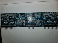
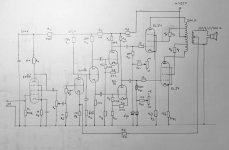
Which one to keep ? Aleph 4 vs Aleph J

What a dilemma !

I've had an Aleph 4 (clone) for a long time and thoroughly love it.

I recently converted it to balanced operation and have paired it with an Aleph P1.7 (clone).

Whilst going through my spares bin I found enough components to build an Aleph J (clone).

Now I've got them both working I'm undecided which one to keep.

The Aleph 4 does have more punch when running at full power, and yes occasionally I do run it at 100W.

However, the difference between the 25W Aleph J and the 100W Aleph 4 is really marginal and is probably not audible at those volumes.

The Aleph J uses considerably less power and in my instance runs at a very cool 40C - the heatsinks are enormous. The Aleph 4 runs at about 60C.

I've not seen a review where anyone has compared the two.

The Aleph 4 did cook its PSU but now has a remote PSU. The Aleph J is self contained.

The two amplifiers are both really pleasant to listen to.

I do feel that the Aleph J is the better of the two at normal low level listening level, which is where it is normally used.

I'm listening with a pair of B&W CM8 Series 2 speakers.

I'm an advocate of having NOTHING in the speaker path, no relays.

One thing I do notice is that the Aleph 4 retires more gracefully than the Aleph J. Neither are terrible though.

Pass X 150.8 Technical information

Hi everyone.
I'd like some information about the ending being discussed.
I have the aforementioned final pass x 150.8 and I would like to pilot the MG 3.7 magneplanars.
as these isodynamic speakers drop down to 2 ohms (and on the technical characteristics of the passage x 150.8 I find nothing about loads below 4 ohms) I would like to know if such a load can be difficult for the final. Finally I would like to know if the power is sufficient for the type of speaker.
Thanks and sorry my english.

Noobie PSU question: PreAmp build (Classic One)

Hello DIY,

Two Quick questions on this PSU Build
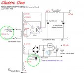
I have circled in green on the PSU schematic image: what Im referring to

Question 1:

C10: 1uF/250V Capacitor after the bridge rectifier:

I'm unfamiliar with this being there, is it some sort of bleeder/filtering device?
It goes straight to ground and its voltage rating is so high (DC/AC)?
Is there a part recommendation i can use for this? -

I have a few of these in my parts bin:

QXK2J105KTP | Nichicon 1μF Polyester Capacitor PET 250 V ac, 630 V dc +-10% XK Series Radial | RS Components


Question 2:

I have the transformers
I noticed they are 230v (where as, in Australia we have 240V AC mains)

I connected them and they work fine, but the power higher on all the secondaries as a consequence....the only reason this bothers me is i know that BIAS is real important in this project,
I know it is no big deal with the regulated heater cct.

But the Tube Rectifier and the supply going to the Amp Valves will be higher Volt - Maybe under load this does not matter? Or it is easy fix with a resistor in series??


If you would like me to clarify anything more please let me know also!


Here is the links of the Full Build and PDFs ect

http://www.triodedick.com

http://www.triodedick.com/classic_1/classic_one_schema_versterker.GIF

http://www.triodedick.com/classic_1/classic_one_schema_voeding.GIF

Attachments

  • Screen Shot 2019-02-12 at 2.32.21 pm copy.jpg
    Screen Shot 2019-02-12 at 2.32.21 pm copy.jpg
    95.6 KB · Views: 134

Switching between sources

Hi there,

I'm building a dac that will have a tube output buffer. I want to make the tube output buffer optional - so I want to wire the output of the dac to a switch that will either pass the dac directly out to the rear RCA's or pass the signal to the tube buffer and then to the RCA's.

I'm thinking something like this will work, but I've never done this before so I thought I'd pitch it to the forum and see if someone had a better idea or could point out a problem with my plan.

Thanks!

Piping multi-channel signal

Hi,

I'm trying to play 32-channel WAV file on Raspberry Pi 3:

Code:
$ aplay untitled.wav
Playing WAVE 'untitled.wav' : Signed 16 bit Little Endian, Rate 44100 Hz, Channels 32
At the same time I'm piping the signal to the named pipe using ALSA 'file' plugin:

Code:
pcm.!default {
  type plug
  slave.pcm mypcm;
}
ctl.!default {
  type hw card 0
}
pcm.mypcm {
  type file
  slave.pcm "plughw:0,0"
  file /home/pi/myfifo
  format raw
}
I'm reading from the pipe using the following Python script:

Code:
import os
import time

pipe = os.open("/home/pi/myfifo",  os.O_RDONLY | os.O_NONBLOCK)
while True:
    try:
        data = os.read(pipe, 400000)
    except Exception as e:
        pass
    time.sleep(0.001)
The file length is 30 sec. The sound in speaker stops after 30 seconds but aplay still running for another 30 seconds. Is it because the 'file' plugin is not quick enough to handle the signal? Thanks!

18" Coaxial driver pair for sale

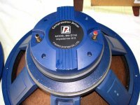
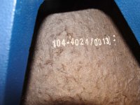
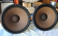
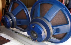
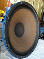
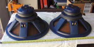
For sale: A pair (two) P.Audio BM Series 18” coaxial drivers. Price for quick sale at $750 (USD) for the pair. These legendary drivers are no longer made and now a rare find. P.Audio no longer offers BM Series 12”, 15” or 18” coaxials. The 18” is model number BM-18CX38. Manufactured in June, 2007. Originally purchased in late 2008. All original.

This is a coax driver with 18” woofer and 1.4” exit compression driver attached. Condition is used. Mechanically excellent, but as these were used for audiophile demonstration purposes, they do show some cosmetic wear. Please refer to photos. They have a very low play time with low powered amplifiers and have never been used in a professional application. One owner.

T/S parameters for the woofer section are measured as:
Woofer “A” Woofer “B”

Re (ohms) 7.63 7.59
Fs 37.9 38.7
Vas (liters) 457 469
Qts .44 .46
Power (RMS) 350 350
X-max 4.5 4.5
SD (sq. cm) 1244 1244
Voice coil 4” 4”
Ref efficiency 99.2 db/watt/meter

H.F. driver is P.Audio BMD740

H.F. DCR 6.63 6.56
H.F. F/S 498 528
Voice coil 3” 3”
Factory rated @ 75 watts RMS @ 500 Hz

H.F. is loaded by a 3.25” exit tapered coax short horn and 16” woofer cone. Loads down to 800 Hz.

I have used these on open baffles of 22” W X 50” H with 8” wings where they work surprisingly well down to about 45 Hz with proper crossover. They will also work well in a large 140 liter stuffed and sealed box down to about 49 Hz -6dB. Add a sub- woofer if you feel the need. However, most music does not require a sub.

Also good in a 300 liter ported enclosure (Thiele QT alignment) with a 12” dia. port 11” long tuned to 37 Hz. (-3db)

The best description of these is that are a “real man’s speaker - nothing wimpy here”. Real life dynamics, scale, force.

I have owned, at one time or another, several 15” Altec duplex coaxials, i.e., 604 D, E & K and 605 A&B. Set up properly, the BM18 is easily superior overall and vastly superior in bass extension, midrange dynamics and smoothness.

I’m selling these simply because I have way too many speakers and need to clean house. It’s time to let these go to a good home where they will make someone very happy.

They will be shipped in 2 boxes by your choice of carrier. Each box is 20” x 20” x 11”. Shipping weight of each box is approximately 50 pounds. Buyer pays actual shipping costs and insurance from Texas zip code 78028.

Attachments

  • coax-1.jpg
    coax-1.jpg
    96.1 KB · Views: 561
  • coax-2.jpg
    coax-2.jpg
    75.3 KB · Views: 551
  • coax-3.jpg
    coax-3.jpg
    92.3 KB · Views: 552
  • coax-4.jpg
    coax-4.jpg
    90.8 KB · Views: 549
  • coax-5.jpg
    coax-5.jpg
    110.5 KB · Views: 545
  • coax-6.jpg
    coax-6.jpg
    67.4 KB · Views: 248
  • coax-7.jpg
    coax-7.jpg
    61.8 KB · Views: 240

Thoughts about the ultimate ES9038Q2M board.

Yeah, I know, the market is full of less than $50 chinese ES9038Q2M boards with performance 10-100 times worse than that DAC promises, and I don't want to think about one more stupid board. I think about the best of possible implementation to get all that promised by ESS. How to reach that aim? Let's discuss.

1) The power management. I believe, to power DAC (SNR -129dbA) with hard-switching SMPS is an inherently wrong idea. USB power itself is convenient and compact but required a silent resonant LLC converter 5V to +/-10-15V with tens pF of Y-capacitance range.

2) DAC side has to be isolated(ISO7240M) from USB/I2S-DSD "bridge". I prefer XMOS bridge, XU208 is fine.

3) Analog 3.3V DAC rail. Ideally, there needs the best low noise opamp(OPA1612 etc) tied directly(of course with some facilities to avoid self-oscillation) to AVCC. Alternatively, good low-noise LDO with extensive capacitors tank will do a great job too.

4) The clock. As I noticed, ES9038Q2M THD and SNR performances only slightly depend on the clock quality. Rather clock's power rail ripples affect THD+N if oscillator IC has low PSRR. So I believe separated good quality LDO with extensive capacitors tank will provide 99% of possible quality with inexpensive MEMS clock(SiT8209).

5) I/U OPA1612 or similar with 600ohm feedback resistor and some preliminary passive LPF before I/U stage(ES9038Q2M has quite big out-band noise). Gain stage combined with LPF 50-80kHz, OPA1612 probably composite but not necessary yet.

6) Output XLR balanced, ideally if with a big-good permalloy trafo. Unbalanced RCA only optional, personally, I see no reason on it.

7) Geek's features.

a) It's quite easy to add BLE iOS/Android interface to control
ES9038Q2M's registers form the app. All registers are available to
control on the fly, and some of them are really interesting(THD
compensation, PLL speed, MCLK divider).

b) THD calibration. ES9038Q2M has 2 registers for 2nd and 3rd harmonics compensation.
I see two way for individually THD calibration. The first one could be performed only
once during the production stage, special AP analyzer script + host MCU firmware.
Very simple and inexpensive but only once. The second way allows you to calibrate
your DAC any time you wish but requires to build precise enough THD analyzer onboard.
I believe this one would be quite WOW. To implement that feature need 1pcs extra
opamp IC and inexpensive DSP(I guess ADAU1761 is fine) + CC2540 as BLE iOS/Android
interface and host MCU to read the calibration result on your phone.

8) Something else?(only don't talk about BT stream, please).

IMF TLS 50 II driver replacements

Hi DIYA,

I acquired a fantastic pair of IMF TLS 50 II's recently and unfortunately some of the drivers have been replaced. They still have the original Audax 12X8 D25 tweeters and Kef B200 woofers, but the one midrange and the supertweeters are different. I'm looking for some input on what I can do about the midrange drivers because I am quite happy with the supertweeters. Unfortunately though the midrange was replaced with something that sort of was just slapped in and this needs to be remedied. It looks like the other midrange is still original.

If someone might be able to tell me what midrange the original driver is that would help.

Here are some pictures:

An externally hosted image should be here but it was not working when we last tested it.

An externally hosted image should be here but it was not working when we last tested it.


Honestly, I'm not sure which one is the original and which one is the replacement!

Thank you for any and all help.

Creek 5050 schematic

My dear old Creek 5050 has blown its output transistors and its drivers (14 transistors in total). It has taken some resistors out too and one zener is open circuit. I can easily replace the transistors but the resistors are blackened beyond recognition and the zener cannot be identified. The only way to sort this out is to look at the circuit diagram but I cannot find it and Creek are no help. Can anybody help with the power output stage circuit diagram? I have never had an amplifier go into thermal runaway on both channels at the same time. All power supply voltages are correct and there was no overheating before this happened.

Philips CD-303 white noise and poppin during playback

Hi all,
after massive resoldering lots of broken pins on all the PCB of my Philips CD-303, It come back to life after 34 years.
Everything works fine exept for the audio output.
As soon as i switch on the player, on both channels appears a loud "hum"; when CD playing starts a lot of popping comes from both channels too.
I put a link of a video I made to clarify the problem:

IMG_8003 - Streamable


I tried with different inputs in amplificator and different CDs with the same results.
Searched the whole forum to find similar problems but they seem related only to one channel.
I would be glad if someone could lead me in diagnosing and solving the proble,
I am not specialist, I don't know what could be the faulty components.
Many thanks and regards!

REW problem. High frequencies are cut no mather what I do

Hi.
I have problem with REW, but only on laptops. I want basic 20-20Khz sweep. So I set it up, run it, I clearly hear it going to the high frequencies.
Then I look at results and for some reason one laptop rolls off everything over 6Khz (lets call it i7), and very old laptop rolls of at 7khz.


Desktop PC works fine to 20-20khz, no problems.
TWO laptops only go to 6 and 7khz.
I used that i7 laptop for measurements some time ago. And it was fine.
Mic is WM61A S.L. recipe. But i cant imagine how it would decide to perfectly destroy high frequencies ONLY on two laptops I tried, but still work fine on desktop. So I am sure that mic is fine.

Since I can hear sweep going way above 7khz (my ears are capable of almost 18Khz), then it must be something with inputs on those laptops. But i7 was fine all the time. Old one I dont know, I just tried it only because this isue.
i7 - Win10
old one - WinXP

This is extremely anoying and ruins everything, since i cant just carry 15kg desktop PC around 😡

I tried to describe the problem as good as I can. Sorry if I reapeated myself
Photos for ilustration:


IMG-20200528-173541 — ImgBB
IMG-20200528-173831 — ImgBB
IMG-20200528-173915 — ImgBB
IMG-20200528-173929 — ImgBB
Desktop PC works fine:
[url]https://ibb.co/YjsZNWY

[/URL]

Low gain LM3886 with lead-lag compensation. Bad idea?

I'm working on a design that uses the LM3886 as the differential stage in an instrumentation amplifier. Obviously, there are some theoretical advantages to using the input buffers to provide most of the gain. I don't know much about external compensation (I've only used unity-gain stable opamps before), but I've been playing around with spice simulations and it looks like the LM3886 can be configured for 4V/V if a lead-lag compensator is used. The phase margin is roughly the same as 10V/V without external compensation.


Is this a bad idea? Bound to oscillate? Assuming it is stable, would you expect any actual measured improvement over a 10V/V configuration?

I2C Volume Control

Hello everyone,


I am trying to build a small headphone amplifier based on the TPA6130A2. It has I2C control pins on it so I thought maybe it would be cool to have buttons to control the volume. For example like the ones on your tv remote or phone. Any ideas on how this can be done? I was thinking possibly a digital potentiometer IC but those are only for the twisting knobs and I'm looking more specifically for button control. Any suggestions/thoughts would be greatly appreciated. Cheers guys.

PhiAMP SE ClassA headphone amp

Note: This is a split-off from
lingDAC - cost effective RBCD multibit DAC design


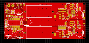
As the PhiDAC hex doesn't drive headphones directly I designed this headphone amp to partner it. Its very simple and has low BOM cost, using the JFET input AD744 with a classA SE output stage. A couple of prototypes have been built and here is the first PCB layout. Would there be any interest in kits of this too? PCB size is 10 * 4.5cm - JLCPCB currently has a special which gets us 5 PCBs for 5RMB, including shipping. Normally shipping alone costs more than this 😀

Attachments

  • 微信图片_20200426175122.png
    微信图片_20200426175122.png
    94.1 KB · Views: 439

Powered Sub Crossover

I am trying to add an old yamaha powered sub (like a YSTFSW050BL but much older and has no crossover as it relies on the amp) to my simple AV system (I have a TV where all inputs go to and I use the ARC channel to a Samsung sound bar). My Sound bar doesn't have a sub output so I have taken the optical out from the TV and pushed it though a small gizmo to turn this into a Left and Right analogue signal, one of which I tried plugging into the back of the sub. It works but it sounds awful, which I assume is because it's getting frequency range that it shouldn't be.

So I tried ordering one of these (NE5532 Low Pass Filter Board Subwoofer Volume Control Board Amplifier Module 9-15V Module Board from Electronic Components & Supplies on banggood.com) but I get nothing out of the module. So either the module is a dud, or I am barking up the wrong tree and I need to find a different solution.

Any ideas if this should work? Or should I look at something like a speaker crossover? (will this work with line level signals?)

Thanks.

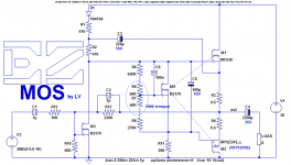
Easy-MOS is a simplistic, efficient and evolutive all-MOS amplifier for beginners

This amplifier is terminally simple, cheap and forgiving, but it remains capable of amplifying in the seventies style: it would have been capable of meeting some HiFi standards of the time.

Of course, nowadays a THD of 0.5% and a full-power bandwidth of 50kHz is only tolerable in audiophile or tube amps, but even compared to a chipamp, it remains easy and accessible.

The design came to birth as a by-product (understand reject) of a request from Daniel: he asked me to design a discrete amplifier that could match a chipamp in performance, simplicity and ease of construction.
I examined a number of options, and I rejected this one because of its inverting design and its (relatively) low performances: in its best implementation, it manages 0.1% THD and 100kHz power bandwidth.

It is nevertheless a neat and effective amplifier, and importantly, it is highly evolutive: this is the plain vanilla version, but serious improvements are possible without too many complications; more on that later.

The main drawback of ultra-simple MOS-followers based amps is their output voltage swing heavily curtailed by the MOS threshold voltage, typically several volts under load.
Add the inevitable losses from the source resistors and the drivers and you are left with an output of Vrail minus 5 to 10V for each rail.
For high-power amps, the loss is relatively benign, but with 10 or 15V of total supply voltage, practically nothing is left to drive the load.

EZ-MOS solves the problem by bootstrapping for the positive rail and a "bias memory cap" for the negative one (or GND for a simple amplifier like this one).

The result is a 3-transistor + bias topology capable of swinging 28.5Vpp with a 31V supply: not bad for a simple follower-based amp.

One of the main drawback is the inverting configuration, but even renowned designers like Renardson use it.

attachment.php


Here are pics of my prototype:

attachment.php


attachment.php


The low-power MOSfets can be almost any low-power type like 2N7000, and the OP can be any approximate complementary vertical pair.


My prototype is wired for a ~30V supply and is capable of putting out ~12W @ 8Ω, but other voltages and load impedances are possible just by scaling R13.

You can probably notice that the board is heavily populated compared to the schematic: that's because of the evolutive aspect.
The prototype includes all the options, but here the jumpers are in the "plain vanilla" position.
More will follow

Here is the 10kHz, large signal squarewave response:

attachment.php


Not blindingly fast for this version obviously, but clean and sufficient for audio purposes, at least in principle.
The simulated THD is a shade over 0.5%; in the same conditions, the measured THD is a shade under 0.5%, thus very close, which is normal for "high" THD levels.
Attachments

  • EZmos0.png
    EZmos0.png
    23.9 KB · Views: 3,910
  • EZmos1.jpg
    EZmos1.jpg
    428.2 KB · Views: 3,624
  • EZmos2.jpg
    EZmos2.jpg
    434.4 KB · Views: 3,638
  • EZmos3.jpg
    EZmos3.jpg
    292.5 KB · Views: 3,790
  • EZmos.asc
    EZmos.asc
    5.5 KB · Views: 150

Markaudio 10m3 build

Following on form the thread below:

https://www.diyaudio.com/forums/full-range/354691-surprised-tangband-w3-fr-future.html

I ordered a set of the markaudio drivers and built up a set of cabs based largely around this design:

Mark Audio Alpair 10.3 Compact Bass Reflex Speaker Build | Mister Wireless

My own version has the same volume, similar dimensions (give or take 1cm based on MDF I already had cut), offset placement of drivers and a 50mm port tuned to ~45Hz.

Built up and speakers mounted, no finish applied yet and no internal damping materials.
I'm using them with a velodyne microvee sub and its ~100Hz internal xover to roll the bass off of the 10m3s.
How do they sound? Not too shabby.
There are comments that the driver has pronounced energy in the 5-7kHz range and some people use a simple LRC notch to attenuate this. Certainly, vocals can be overly sibilant and, to my ears, they get a bit fatiguing when turned up.

Measurement suggests that this is not so much a bump at 5-7kHz as it is cone break up causing exaggerated energy around this frequency range (you see a comb like series of peaks and troughs between 5kHz and 7kHz). I tried an active filter with a 0.7Q notch @ ~6kHz and this does reduce sibilance but also reduces desirable content in this frequency range. I'm hoping that a bit of internal damping material will help here and reduce the need for the notch filter.

Nothing like throwing additional complexity at a problem though so I looped in my minidsp DDRC24 and ran the Dirac Live 2.0 room correction software. This did an incredible job of smoothing out the high mids without sacrificing detail. It can still get a bit fatiguing when cranked up but, as I say, maybe internal damping material and a bit more burn in will help.

To really balance them out though I needed to give a wee bit of boost above 12kHz and a bit of baffle step compensation from ~200Hz down.

With miniDSP I have to say they are now fairly incredible. I was lucky enough to have mdf, ports and terminals left over from an old build so only needed to buy the drivers (£110 on eBay). For the cash they are an absolute steal.

My previous speakers are a set of ATC SCM11s which I'd previously thought to be untouchable. However, the vocals coming out of these wee FR drivers surpass the ATCs easily. All told, If I had to choose one set of speakers (and I might), I think the Markaudios might have it.

Surprised and delighted by the results.

Should I find time this week, I'll add some internal damping material and see what effect that has. Will report back.

Cheers,

iep

Repairing diaphragm on 15" Driver?

Hi All.

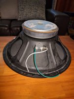
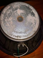
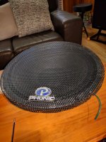
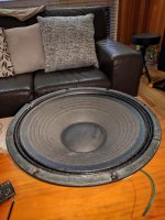
Came across this 15" Phonic Woofer marked "341-15058-610-0 15" 6Ω 225W".

I'm not familiar with Phonic speakers, and don't know whether this driver is for PA, or hifi?

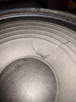
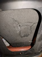
There's a tear on the paper diaphragm.

Is this repairable?

How would I go about re gluing it?

Is this driver worth repurposing?

If it can be successfully repaired, I was thinking of using it in a simple DIY Subwoofer build.

I would mostly use it in a 2.1 hifi system, or as part of a sound surround set up.

Alternatively, is there a market for the driver itself?

cheers

Cliff

Attachments

  • Phonic woofer 1.jpg
    Phonic woofer 1.jpg
    622.2 KB · Views: 151
  • Phonic woofer 2.jpg
    Phonic woofer 2.jpg
    401.8 KB · Views: 141
  • Phonic woofer 3.jpg
    Phonic woofer 3.jpg
    544.6 KB · Views: 136
  • Phonic woofer 6.jpg
    Phonic woofer 6.jpg
    542.1 KB · Views: 127
  • Phonic woofer 7.jpg
    Phonic woofer 7.jpg
    433.8 KB · Views: 129
  • Phonic woofer 4.jpg
    Phonic woofer 4.jpg
    457.6 KB · Views: 80

DIY Spotify / Chromecast player

I am currently looking for a new streaming solution but I can’t seem to find one that is able to satisfy what seems to be simple requirements:
1. Gapless playback from Spotify connect and Tidal.
2. Supports Chromecast or other multi room playback, does not need to be gapless.
3. Lets me use my Spotify playlists.
4. Digital output I2S, SPDif or Toslink for external DAC.
5. Doesn’t require a software engineering degree to be set up.

Basically I want to build my own Naim Uniti Atom. I have looked at solutions like Up2stream and various R pi solutions, but none of them seem to support my own Spotify playlists or gapless playback.

Have I missed anything, or is there another way to integrate these streaming services to a DIY setup, that is not just a USB or Bluetooth player?

833a Solid State Driving

Hello! I could use some advice:

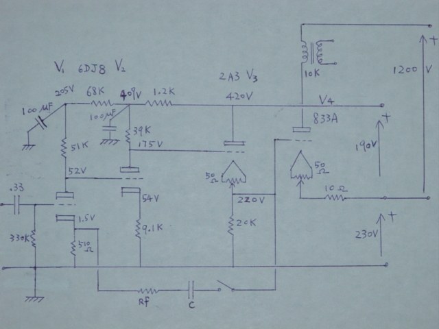
I am looking for a nice and simple solution for driving an 833a tube for audio applications. I am adapting an existing design that was built for hard switching via MOSFET driving. My goal here is to flip a switch to swap between PWM applications to audio amp applications.

What is the most minimal component driver design that can drive an 833a tube?

I am ok with solid state!

I can also get down with direct-drive tube drivers like this:
833Acct.jpg


-Kyle

Attachments

  • 311b.png
    311b.png
    459 KB · Views: 584

Difference between DC Link and AC Filtering MKP's

I have searched here and the net, but there is hardly any detailed information.

What is the fundamental difference between a DC-Link MKP vs. an "ordinary" AC filtering MKP ?
For example, Roederstein MKP1848 vs MKP1840M.
Apart from small differences in loss factor, and a lower dV/dt, I cannot spot any major differences.

What is the underlying difference in the construction of the capacitor ?


Thanks in advance,
Patrick

JL Audio 300/4 Repair?

I know I know, it's old, but I love this amp!
I've never had a problem with this amp until now. The power turns on just fine and the sound works at first. When the amp warms up after a minute the output boards are turning off. LED's on the boards themselves. The main power is still on.
Any heads up on where I should be searching for the bad component?
I've searched the rest of the forum and have tried the few things listed but to no avail....HELP!!!! 🙂

Making some full range speakers, critique!

I have recently made my second ever pair of speakers, this time a pair of ported full range numbers based on fostex FE126NV. I have a short video of the construction YouTube

I did my sums + stuck my finger in the air only when needed - but I really need to test them properly. I can see one is able to get test programs that will do a sweep through the audible sound spectrum and plot a nice frequency plot. If I do that with a bog standard cheapie mic and my bog standard computer - is that ok? If not ideal, is it better than nothing?

I'm also interested in critique of the design and construction method. Obvious problems I don't need reminding of is slightly sloppy finishing and, more technically I didn't round over the edges to reduce diffraction (part of the look n feel I'm afraid). Anything else is fair game. I think they sound good enough, but I'm no virtuoso listener.

How big of a back-horn would be usable for a 4-5" FR driver?

I just finished the Fostex BK-12m (Madisound kit), which was a blast. With just a few hours I am loving it and if they improve with break-in I will be in for even more of a treat.

I was wondering - if you had no limitations of space, budget, could you make the horn even larger and get even more bass performance from the same driver (FE126NV in this case)? For the kit I built, the horn is about 6x14" and F3 is rated at 65 Hz. If you had a (properly designed) horn with a 2x, 4x larger opening, could you get even more usable low-frequency response? Or is this driver maxed out in this cabinet?

Thanks!

Cheap battery powered Bluetooth receiver: Are they all the same?

I'm looking for a cheap BT receiver with battery, for my vintage ghettoblaster to make music from my iPhone wireless.
And by cheap I mean one of the no-name (no a requirement of course) Bluetooth dongles for under, lets say, a $50/€45.
This is just a lark and the SQ while decent and use cases of the blaster, doesn't warrant big expenditure.

Are they all the same, or are there some that are clearly better?
Are there things to look out for and models to avoid?

Myryad IM 120 integrated amp

I picked up a Myryad IM 120 integrated last week and have been going through it, as it has had some confusing issues. To start there was a stuck input button (tuner) and there was some distortion when that input was selected. I got the button unstuck with contact cleaner and deoxit, but I found that there was some distortion on some other inputs as well.

The weird thing was that it would clear up. I thought the original problem was in the selector buttons, but looking at the circuit, I see that there are relays and some small film capacitors near the rca jacks. I'm wondering now whether the problem is in the relays and capacitors. Could it be that the capacitors need to reform, if the input has not been used in a long while?

My open baffle dipole with Beyma TPL-150

Me and a friend started out with two large pine boards, and three hours later we had two working dipole speaker prototypes. The fastest speakers I've ever build!

We wanted to have a speaker that is true dipole, without using two tweeters like the Linkwitz Orion. The Beyma TPL-150 with the rear chamber and damper pad removed proved to be perfect! It extends more or less flat to 1.5 kHz. Removing the damper pad (which is glued to the rear side of the driver) produced a 5-6 dB peak around 9 kHz, but that was easy to get rid of with parametric EQ.

The midrange is the same Seas W22EX001 used in the Linkwitz Orion.

For the bottom octaves we are going to use a new 21" from Beyma, which has not yet arrived. This woofer named 21SW1600nd was presented at Prolight and Sound in Frankfurt a month or so ago, and production drivers are expected around the end of May. While we wait, a Beyma 18G50 acts as stand-in. The longthrow 21" will produce at least 6 dB more SPL than the 18G50. Not that the 18" is anyway close to bad... there is plenty of bass down to approx 30 Hz.

XO and EQ is run digitally in my computer. There's a long thread on this forum about that: "A how to for a PC XO". XO frequencies are 150 and 1500 Hz, 4th order slope.

Attachments

  • image0002.jpg
    image0002.jpg
    59.5 KB · Views: 22,210

Parallel Polarized Caps on Horn

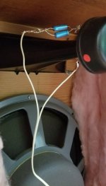
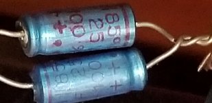
I was asked by a friend if I knew why on a horn speaker he has (part of an older 2 speaker build with a full range 15" J.B. Lansing D13030-17000 Hz and an Oxford 4” X 10” exponential horn 900-20K Hz), does the horn have a pair of 85uF polarized caps in parallel, but soldered together with the negative of one cap with the positive of other at one side (end) of the pair with the other end of the pair the same (+ -) and then on to the speaker. The JBL is being used full range with no crossover and the horn has just the 2 caps in parallel.
He was given a second set of the same speakers and wanted to build another unit but is questioning the capacitor (crossover ?) configuration and I don't know the answer why the 1st build (50 years ago ?), used the cap configuration as shown. Any ideas?
Oxford horn capacitor 1.jpg

Oxford horn capacitor 2.jpg

Headphone socket for thick front plate?

Hi,
I would like to install a jack 6.35mm socket for headphone through a thick front plate (8mm). So far the longest 'going-through' that I found is 9mm long (9-10mm diameter), too short to screw it within the front plate. The other option would be to use a xlr-style socket from outside the plate (but around 20mm diameter).
Wondering if someone knows a non-xlr-style socket that could fit?
Thanks

NAD C300 schematic and/or help...

Since a long time I have a NAD C300 amplifier and I really liked it. It's simple, does (or must I say... Did) what it has to do and sounds pretty good.
But now, he's dead. It happened about a year ago when a leaking roof spilled some water into the PCB. First I heard a noise, like an overdriven sound, then the red LED lit up, what means the amp goes into 'protect mode' and then it failed completely. The two big (5A) fuses were blown and they immediately blow again when the amp is powered. When the PSU is disconnected, they don't blow so it is a short circuit in the main PCB, not in the PSU itsself.
I checked several Big SS-components for short circuits (still soldered on the PCB) and the two big 10.000µF Capacitors but I couldn't find a short.
Does any one have a schematic of this amplifier. I allready tried several NAD dealers and repair shops but I think they don't like to give away this information.
Without a schematic it's really hard to start looking because a lot of components were used in this amp and the faulty one(s) could be everyware...

Grtz J

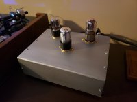
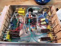
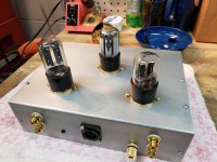
Just finished a Hagerman Cornet octal

I built the Cornet 2 phono stage a long time ago and modded it to an "octal hybrid". Wanted to try the full octal and I had most of the parts on hand. When I built the Cornet 2 I made the power supply in a separate enclosure so I made this to use the same supply.

For those not familiar the Cornet 2 uses 2 12AX7 gain stages and a 12AU7 output, the hybrid replaces the 12AU7 with a 6SN7 and the octal uses 2 6SL7 gain stages and a 6SN7 output.

I made the case from a spare sheet of aluminum and used hardwood floor scraps for the sides.

Sounds great, nice and quiet too.

attachment.php


attachment.php


attachment.php

Attachments

  • completed 6-15-2020.jpg
    completed 6-15-2020.jpg
    96.8 KB · Views: 612
  • inside 6-2020.jpg
    inside 6-2020.jpg
    363.2 KB · Views: 566
  • back 6-2020.jpg
    back 6-2020.jpg
    223 KB · Views: 470

TU-8600S upgrade options

12AX7/ECC83

WE 5755 (with getter version) price is US$40/pc 5755 to 12AX7 adapter included (plastic for TU-8600S, metal for Sunvalley SQ1616/PRE1616)

Raytheon / Western Electric JW-5755 / 420A

https://flic.kr/p/2jcdfKQ


RCA - Clear TOP 12AU7 /ECC82(USA Year 60s) $36

https://flic.kr/p/2jceRMY


MULLARD 12Au7/ECC82 (Great Britain Year 60s/80s) $75

https://flic.kr/p/2jceRN9

Expaination about Mullard 12AU7
https://www.effectrode.com/news/vin...significant event,colour print on their tubes.

Hybrid Tube Amplifier -- Schematic Needed

Hi All,

I picked up this amplifier (well . one like it ) at a local auction.

It was very cheap.!!

Does anyone have the schematic for it??


There are many versions under different names - some with bluetooth.

Specifications
Power Supply: 220V-240V / 50-60Hz
Output power: 25W+25W
Input power: 100W
Input impedance: 47k ohm
Input sensitivity: 300mV
SNR: > 80DB
Frequency response: 28Hz ~ 20KHz
Output impedance: 4 ~ 16ohm
Dimensions(D*W*H): 312 * 270 * 150 mm
Weight: 6Kg
Tube: Beijing 6N1*2 + 6P1*2

Cheers

Attachments

  • Amplifier.png
    Amplifier.png
    349 KB · Views: 446

prototyping solid state output sections

I've got a technique for building prototype output stages for experimentation and testing with solid-state amps that seems to work quite well, so I thought I'd share it - nothing very earth shattering, but seems to work quite well.

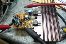
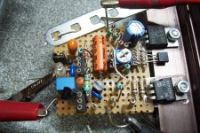
Using stripboard and a chunk of aluminium as a heatsink/thermal mass. I tend to put output devices, drivers, any associated caps/resistors on the board, sometimes the whole bias generator, sometimes just a thermal compensation transistor. The connecting wires are solid-core suitable for direct breadboard insertion.


outstage_proto1.jpg

(note the thermal pads are just kapton tape with a little thermal paste on top!)


outstage_proto2.jpg

This is the latest, an EF output stage using MJE15030/1, NJW3281/1302's.
I've done this also for CFP stage, lateral MOSFET stage, and a quasi-comp IGBT stage.

Some of them included Zobel and inductor, but I've a separate board for that now.

This makes it easy to experiment with amplifier topologies on a breadboard, firstly without the OS, then tie in an OS once that's satisfactory. Less chance of making mistakes (although adjustable current limited supply is useful for that).

I'm thinking of making some little Vbe multipliers that plug into a breadboard too, and generally modularizing to make it easier to play with basic topologies.


For a finished design I would always layout a PCB, this isn't a standard of construction I'd like in a finished amp(!)

Converting my dad's Heathkit EA-3 for guitar

I've been documenting this project on the DIY Amp forum at TDPRI, but I thought that it might be more interesting here, because it strays from the usual build-a-Fender-5E3 content.

My dad passed on 10 years ago this past January, at the ripe old age of 83. On a recent trip back to see my mom, I came across the Heathkit integrated amp that he built in 1961, shortly before they got married. It's in pretty sad shape cosmetically, and hasn't had any service since 1980 (per the service sticker from the Heathkit factory!). It's got no value as a vintage piece, and I've got nowhere to use a 14W mono amp, so I'm converting it for guitar use.

I've done simple things before - cap replacements, simple circuit mods, etc. I know how to follow good safety practices. This is the most involved project that I've undertaken.

The original plan was pretty simple - scrap the input selector and RIAA filter, Fender-ize the front end, and add a PPI MV. And I'm still pretty much in that ballpark, with one major change; I'm changing the third gain stage (6AU6) to a cathode follower. If I leave it as a gain stage, there's just too much gain, and I may want to try alternative tone stacks that load it down more than the Bax does.

I feel like I've got a decent handle on the circuit, based on studying both theory and execution, but there are a few things that aren't entirely clear to me; I'll be asking about those along the way. I'll post the updated schematic in the next comment.

good floor-standers - Troel Gravesen DIY

I love to read about your speakers and 25 years after my first DIY loudpeakers I have to build new one.

Knowing that you it is hard to answering questions regarding sound taste I still hope that you can help me with decisiont. Just some facts:

1. My living room is cca 17m2 connected with dinning room cca 12m2
2. One year ago I bought Naim Atom (40 Wpc) with a lovely sound. I will keep it.
3. Main goal is to listen at the evenings with low volume and I want to have LIVE FEEL of music with deep bass with all details (rock, jazz, no classic)
4. I have a WIFE, so speakers must fit in - I think about slim floor-standers...

I'm thinking about EKTA-mk2 (or similar), TOWT-mk3, Jenzen SEAS ER/CA...
...which is most enjoyable and non fatique speaker (I suppose Ekta is one of them)
...is my amp enough for Ekta mkII (low eficiency...l
I know it is hard but I will really appreciate your suggestions and help

Thank you for answers!

Subs for kick drum range

Hi ya guys and any girls on here, I have four Wharfedale Pro Delta 218B dual 18" subs and two Delta 215 mid/highs, i'm thinking of buying four Delta X15B single 15" subs so I can operate the Delta 218B subs from 30-60hz, the Delta X15B subs from 60-100hz and then the Delta 215 mid/highs from 100hz upwards.


My question is would you think the difference would be good adding the 15" subs for just the kick drum range? My subs are great they go quite low and give you a nice rumble in the stomach but they don't give you that slam for kick drums. I know 15" drivers are better for kick drums so I figured i'd think about adding four Delta X15B subs.


Thanks anyway I really do genuinely apreciate any help you people give me.

Sony TA-F606ES channels unbalanced.

Hi.
This amp got a lower left channel or somewhat a bit "muffled" in the top region. Tried cleaning the volumepot, a 4 pin type with center tap. I took the pot apart and had a look at it, no obvious tracks or other fault. Adjusted the bias to specified 24mV on both channels, no change. Sanded the output relays, same result. Could it be a dry cap or something in the center tap circuit messing up? It´s a nice amplifier, mosfet driver and output stage. I would really like to get it sorted so I can use it for preamp paired with a couple of TA-N55ES. I have the servicemanual if anybody care to take a look at it. It´s not easy to find a new pot either since it´s a 120k type and have the center tap.. 🙁

Volume control for sbc/ i2s DAC

Hi all,

I want build an amp feeded by the arylic board connected to an i2s dac. So the chain will be:

Arylic -> Kali recloker -> I2s Dac -> power amp

I want use Arduino to control the volume by a rotary encoder and from a remote. But I want to be able as well to control it from the Arylic software on the phone.

The dac board (AUDIOPHONICS DAC I-Sabre ES9038Q2M KALI EDITION Raspberry Pi / I2S & SPDIF / PCM DSD - Audiophonics) permit the i2c connection to control volume.

The question is, if I change the volume directly on the Dac, the Arylic board change the volume as well, or the 2 volume are independent? (Dac is set as slave)

Thank you

speakers buzz when sub amp is connected

I don't know if I should post this here or in class D or in subwoofers but I have a subwoofer hooked up to my tube amp through the speaker level inputs. When the amp has the switch on but has gone into standby mode I get a faint buzzing sound out of the speaker it is hooked up to. This has actually happened with two different subs, both class D; the class a/b amp didn't seem to do it.
If I disconnect the amp from the speakers it goes away. If I reverse the speaker wire polarity to the sub amp it doesn't change. Both the main amp and the subwoofer amp are both plugged into the same outlet.
I was already planning to convert the speaker level input to line level and run it through a dayton dsp-lf so that may solve the problem but I'm just curious what might be causing it.

Rework old Mitsubishi ss2100 towers

I've been given a pair of Mitsubishi ss2100, they don't sound very good, 3 way 3" tweeter, 4-4.5" mid, and 10-12" Woofer each no markings on backs of magnets, no damping no crossover ( just 2 unidentified Caps at input) no port, I'm basically a noob been since 1979 last worked on speakers, I want to upgrade, new tweeters, mids add damping, ports? and crossovers, no exact dimension yet roughly 42" tall 14" wide 10-12" deep, no baffles! any ideas? Going to power from Tubelab SSE, 4-15 watts.

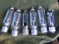
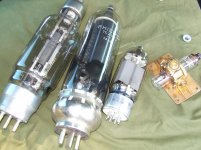
Federal Telegraph F-123-A 125W triode

Any hopes for these bottles? Looking at the limited datasheet it looks like high mu types designed for positive grid drive. ?
I got these when helping cleaning out somebody's closet so to speak.
I think these require 1500V or more to sing well, so I doubt I will ever build with them. Perhaps make a pedestal and just have the filament glowing and have a neat light on the shelf...
The other pic is the big philips transmitter tubes I also got, and same problem with them. An 813 is on the right for size.

Attachments

  • F123A.jpg
    F123A.jpg
    561.5 KB · Views: 217
  • Big_philips.jpg
    Big_philips.jpg
    569.7 KB · Views: 212
  • f123a.pdf
    f123a.pdf
    1.2 MB · Views: 137

High end speaker elements?

Hello,

I’m on a lookout for speakers for DIY project, and i wanted to ask for recommendations - what companies produce high end speaker elements?

Not looking for specific models of speakers, just companies overall - since i have no idea really. I only somewhat familiar with Celestion and Dynaudio.

Basically aiming to build 3 way floor standing speakers, preferably with 15’’ woofer, 12’’ will do also, but not less. No compression drivers - just dome speakers.

Thank you

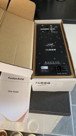
FS: Hypex Fusion FA253 Plate Amp plus remote kit

FS: Hypex Fusion FA253 Plate Amp plus remote kit - price drop

Got one of these used off a friend to try out recently.

Very pleased with how it sounded and to my ears improved on the standard passive crossover he created. However my plans to go active on front three have changed, I'm just not going to have the funds to buy another two.

So with regret selling this.

Perfect condition, fully functional, hasn't missed a beat in the month or so I have had it. Has remote kit and remote.

Would prefer a UK buyer for shipping reasons but will post to Europe if need be.

Looking for £300/€335 plus shipping.

Attachments

  • image0.jpg
    image0.jpg
    482.5 KB · Views: 556

Headphones' varied impedances and USB limited power => class G adsl drivers ?

The recent discussion on headphones' largely different impedances and their varied voltage requirements got me thinking. So, a bit of brainstorming...

USB ports and chargers are widely available but the current they can deliver is often quite limited. When I designed a small DAC+amp made to be entirely usb powered from a laptop port, I had the choice between using a dc-dc converter at either +/-5V or +/-9 or 12V. The first had enough current for low impedance headphones, the second enough voltage for high impedance headphones. But the reverse wasn't true. Since I mostly use hd650, no big deal at the time.

But for the sake of universality, a chipset like the ths6032 looks perfect. It's an adsl line driver so it's designed to drive low impedance loads at low distortion. It incorporates a class G system so we can use a low current/high voltage supply for high impedance headphones (or even small bursts of high power in lower impedance ones) and a beefier low voltage supply for low impedance headphones while staying in a smaller power budget. And I see no reason at first sight why it couldn't be used in multiloop to provide ease of integration and guarantee proper audio performances. As it is a current feedback amp, it offers a further degree of play for compensation.

I'm honestly a bit surprised to see how little attention the ths6032 (a quite old device) has received compared to the tpa6120a2 (only 2 hits in the whole forum).

Your thoughts ?

Adding reverb to amplifier

Hi I came in the possession of a very nice tube amplifier, used previously in a nearby church, I have painstakingly reversed engineered the circuit, see attachment. It has been beautifully built, top quality components, all wiring neatly twisted and bound, the guy must have been a semi-professional.
I want to give it to my son so he can use it as a guitar amplifier. Yes I am aware of the differences, this amp has been built for low distortion, not what you need from a guitar amp. I have seen circuits where they create a parallel signal path with a reverb tank. Maybe I could do that after the EF86? Or ‘do something’ withe the feedback loop? Suggestions and advice are very welcome.

Attachments

  • C633A746-7EB1-488E-8E51-650376C512D8.jpeg
    C633A746-7EB1-488E-8E51-650376C512D8.jpeg
    534.2 KB · Views: 264

Onkyo TX-SR577

Hi Peeps,

I have been trying to fix my broken reciever.

Its a Onkyo TX-SR577, its quite old, but it was working fine.

I think basically the centre channel has had it.

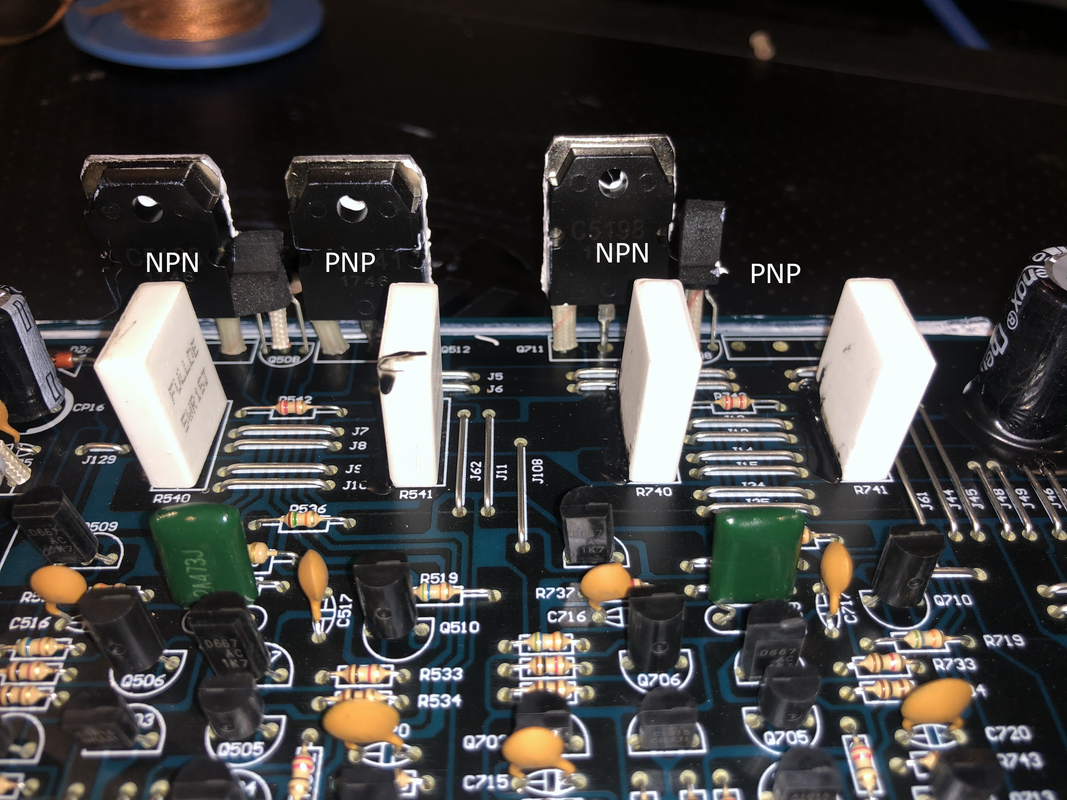
There are two very burnt looking transistors and i am trying to identify the correct parts.


I have no knowledge, and was hoping if someone could tell me if it looks like i am going to get the right parts or had any other tips.


1. TOSHIBA C5198 931
https://uk.farnell.com/on-semiconduc...00w/dp/3368621


2 PHR MPR 2w R22K X2
https://uk.farnell.com/cgs-te-connec...ound/dp/987499

There is clear evidence of the magic smoke come from certainly the TOSHIBA compnent and possibly the PHR MPR 2w R22K X2. However, that just might have burn marks because of the proximity.


I found a similar post: but it doesnt provide a good description of the parts.
Transistors and emitter resistor for ONKYO TX-SR506 AV Receiver


Any help anyone can offer will be greatly recieved.

Do i need a special thermal grease or flux, or is any old thing ok?


Thanks
Adrian


I posted this in solid state, but wasnt sure that was the right section.
Projects by fanatics, for fanatics
Get answers and advice for everyone wanting to learn the art of audio.
Join the Community
507,753
Members
7,886,663
Messages

Filter

Forum Statistics

Threads
406,157
Messages
7,886,663
Members
507,753
Latest member
ayodej