Where exactly to measure difference (cm) tweeter and woofer

Dear fellow forum members,

I am currently preparing for another day of measuring my diy B&W CM8 S2 with FA-123 hypex plate (also converted to sealed model by removing bass reflex port).

Apart from experimenting with placing absorbing materials in the middle instead of the sides (the 'burrito approach'), I would also like to experiment with resetting the crossover frequencies and type of linkwitz riley filter (LR2, 4, 8 & 16).

To my (very limited) understanding, when working with LR filters, it's important to have the cones (tweeter, mid and woofer) properly alligned.
In order to do that, I have to measure the distance between the cones and a fixed point (e.g. the front of the speaker). However, the cones of the drivers of the B&W CM8 S2 are very different in design.

Where exactly do you need to measure?
See https://www.homecinemamagazine.nl/wp-content/uploads/2015/05/BW-CM-S2-review-7-770x449.jpg for a photo of the speakers.

In the past I've used the 'invert' option on the plate amps to determine the delay in the tweeter by seeing a dip at the crossover frequency (using LR4 filters). However, this was done after designing the crossovers and I'd like to implement the tweeter delay before the design.

Any tips? Thanks!
  • Like
Reactions: svp

Audio Precision Portable One Plus for sale.

Audio Precision P1P looking for a new home. This is the standard unit i.e single domain, no extras. In good working order and passes it's self test with no errors. A few scuffs on the outside but hey it's a portable....that's why it has a ruggedised case.

Will add in whatever cables/adaptors you need as I have more than I care to count. Will also include some 3mm/6mm neoprene sheet as the P1P feet are known for getting knocked off in the field.

Based in the UK and it weighs 9kg so keep this in mind if ordering from elsewhere.

Offers around £1000.

Attachments

  • DSCN0108small.jpg
    DSCN0108small.jpg
    682.9 KB · Views: 198
  • DSCN0109small.jpg
    DSCN0109small.jpg
    659 KB · Views: 182
  • 20200312_114025small.jpg
    20200312_114025small.jpg
    720.8 KB · Views: 201

Pioneer SA-7800 Power Assembly Variations

Hello, I hope this message finds everybody well.
I recently embarked on two Pioneer Sa-7800 amplifiers: both in the HG version (i.e the 220V one, not the 120V one).
I noticed that the power assembly PCB is different for the two models, so I was wondering why?

The power assembly of the 1st amplifier is marked as "GWR-114" which is the ref. number in the schematics of several service manuals online.

The power assembly of the 2nd Amplifier, instead, is makes as "GWR-115", or GWR-1150. I can't trace back this number from anywhere.
The PCB looks similar to the previous, except for the fact there are only two fuses instead of three (the 3.15A is missing). The transformer also has a different part number, whereas the big caps are not from Nichicon.
This amplifier has a plug with only two pins thus it lacks of the GROUND connection to the chassis (the other has a 3 pins plug + chassis connection to GND). To be honest, I cannot understand how the chassis is earthed.
Yet, everything seems to be working and the chassis is not under voltage.

Apart from that, the two PCBs are very similar and both seem to work.
I guess maybe the 3.15A fuse may have been embedded in the transfo, and that there may have been some evolutions.
If possible, I'd appreciate if someone could confirm this is the case, or if the GWR-115 PCB comes from another Pioneer model.
Thanks for any help.

Fender Bassman 70

Hi


This amplifier works alright, but if I increase the volume above 3, it distorts. I replaced the power tubes, but still the same. I took some readings on the output ultralinear transformer . The right hand side winding has a DC reading of 54.5ohms and dissipates 30mA at 450V plate voltage. The left hand side winding has a DC reading of 32ohms and dissipates 45mA at 450V plate voltage. The bias voltage reads -52V and it is a fixed bias with a bias balance pot. I guess that the distortion is due to the inbalance in output power between the 2 tubes caused by the large difference in ouput impedance. I also guess that the left hand side winding has partially shorted (reading 32ohms DC resistance). Can this be the reason for the distortion or something else can be the cause. Please assist. Attached pdf.


Thanks

Attachments

Headphone Amp Kit using 5670 + 6080 tubes - suggestions

Hello All,


I'm populating a PCB I bought from the auction site, advertised as:
"5670/ 6N3 + 6080/ 6N5P Stereo Tube Headphone Amplifier Heisang Amp Circuit PCB"


Link here:

5670/ 6N3 + 6080/ 6N5P Stereo Tube Headphone Amplifier Heisang Amp Circuit PCB | eBay


PCB came with the following schematic:
attachment.php


It seems to be an SRPP configuration with a cathode follower.
Filaments are all AC powered.


I 'm particularly puzzled by the 6.3 (1A) supply.

Instead of just feeding the 5670 filaments it keeps going to a couple 100Ω resistors and then it connects to ground and on to the B+ supply via a 100KΩ resistor. I'm no expert here so please help explain what's the purpose of all that (if any)? I plan running DC supply to the heaters but I'm wondering if I need to change something in the process.


Also, any suggestions towards improving this design are very welcome.
It is a cheap little kit but I'm going to give it a try.


I think Douk sells it as Little Bear P7 in a completed form.
Will add some pictures later.


Thank you all for reading.

Attachments

  • PCB.jpg
    PCB.jpg
    131.2 KB · Views: 6,638

replacing pcm1716 with wm8740 ??

Hi all. 🙂

I have a cd player that uses the pcm1716 dac and I thought that maybe it could use a better chip to achieve better sound. I found the wolfson wm8717 and wm8740 as a pin by pin replacements, and I would like to know if it is a good idea to replace the pcm1716 with the wm8740.

Here is a link to the wm8740 specs -> http://www.wolfsonmicro.com/product.asp?pid=7

And this links to the pcm1716 .. -> http://focus.ti.com/docs/prod/productfolder.jhtml?genericPartNumber=PCM1716


if anyone has a better replacement chip idea… let me know…

thanks
m.

New "Hi-End" Op-Amp Module: AS402

This is from AS “АLFA RPAR” a company I've been following in recent years due to its bringing back analog synthesizer chips and related analog semiconductors that were discontinued by other manufacturers over the decades. Other than having received a few samples of the synth chips, I have no relation to the company.

I don't know if the '402' number means anything, but this company has often used previous part numbers for its products, such as AS394 for its equivalent of the LM394 supermatched transistor pair.

Hi-end audio bipolar input amplifierr

Knowing which components really matter to SQ and those that dont

I read in various articles sometimes it is mentioned that forninstance 'put as good resistor/capacitor here as you can afford'.....and other times in certain locations the quality of the component is less important.

To narrow this down to 2 instances....I read an article on improving the crossover in a B&W speaker. Is it that a component directly in series in the audiopath is deemed important...and is it that an R or C shunted to ground is less important?

Also I want to build this active low pass filter board and it has loads of resistors. I can't follow the schematic all the way as is passes through various op amps and potentiometers, but assuming I can decipher it...I take a similar view to the XO and anything in direct series to the signal output should be the best quality one can muster? The others less important?

Thanks in advance. Just wanting to get a handle on where to better spend my money and where not to waste!

transformer hum cure ?

Hello , I just purchased an Amber series 70 power amplifier . It sound very good but has a transformer hum audible from 3 ft away . No speaker noise , just mechanical . A friend audiophile says his Parasound has the same issue , a tech friend wrapped the transformer in mortite insulation tape . Noise now inaudible . He suggests this for my amp . Seems to me like a recipe for an overheating transformer . Any ideas on this anyone. thanks in advance

Door speakers stopped working.

What’s up guys I have a 2014 ram I upgraded my 4 door speakers on to some Rockford fosgate 6x9’s and I also installed a 10” sub. I kept the head unit identified the speaker wires behind the head unit and ran them back to a 5 channel little skar amp I got via a LOC and then ran the post amp wires back to where I intercepted the wires. Didn’t upgrade my tweeters and they’re wiring runs in parallel to the front doors. Recently had system disconnected for a couple days reference removing the seats and some work being done on the car and when I hooked amp and wires back up my front door speakers on both sides don’t work the tweeters still work though. I checked the wiring and nothing I’m puzzled as to what to do or to have any idea what might be wrong. Any one can help me out ? For what it’s worth the amp isn’t very strong I think it’s 650 watts over 5 channels but it’s only pushing these 4 6x9s and 1 10” on its 5th mono channel.

Sansui 5000a help

Repairing this reciever and the signal looks good on the scope until I connected a speaker at which point it becomes severely distorted. The scope shows almost a 35v ptop signal without speaker, with the speaker its more like 2v peak to peak. You can see the voltages sag on the driver transistors base and emitters. The collector stays fairly constant. I disconnected and check the finals and they are good. All driver transistors test good. Emitter resistors are good. Head scratcher... any advice? I know these are notorious for bad driver boards. One of them I rebuilt and the other was still good but both boards act the same.

question about speaker A speaker B switching

Don't know if I'm posting in the proper forum but here I go... I have 2 msr250 rca dimensia amps. They use a stk4192 II chip,so I'm posting in chip amp. The problems I'm having is with the speaker selection. One amp the A speakers have a problem,the other the b speakers have the same problem. When I first tested the A problem when I moved the receiver to just check I was on the correct input the speakers started to work. Jiggling slightly would cause them to be sporadic. Same with the other receiver except on B speakers. I'm thinking the mechanical switches for the speakers are mounted to the pc board and then have "extensions" going to the front panel so there is some stress on the switches and I'm thinking maybe the solder joints are bad/cracked/broken. I don't do much amp repair but have a couple times seen situations where switches soldered to the board like that eventually get the solder joints bad.
I don't have any schematics but I got wondering, are those switches the only thing that send the signal directly to the speaker output terminals or does it just send a signal somewhere and from there it goes where ever and eventually to the terminals?
I haven't looked at the back of the pc board yet to examine the solder joints but I've been curious about how the speaker selection works.
At first I thought maybe the switch was broken or faulty but with the cover removed the switch looks fine and appears to be working properly. I also tried getting some de-oxit into the switch. I then bought the second receiver just trying to get a receiver with both speaker sets working,but the second receiver pretty much has the same problem but on speaker B.

My Review of the Audio Technica AT-LP120X-USB Turntable

The AT-LP120XUSB is an updated offering of the former AT-LP120 that retails for ~$250 with the factory mounted AT-VM95E cartridge. Typically considered an entry level table, it's not exactly a revered high-end turntable in audiophile circles, but is capable of excellent sound. Some feel that it's a cheapened version of the LP120, but it still weighs a respectable 17 pounds, and offers some significant upgrades that lend themselves to improved sound.

The tonearm and drive method are unchanged, and are identical to those on the LP140XP. One of the most significant improvements is a fix for the built in phono preamp - it now has an upgraded defeat-able switch and is no longer problematic. It can still also be hooked up to an outboard phono preamp of your choice. Possibly of equal significance is the new stock AT-VM95E elliptical cartridge. It's not only a nice upgrade from the former AT-95E, but there are three impressive full diamond shank (nude) stylus upgrades that are plug and play replacements - 1. VMN95EN (nude elliptical- $99), 2. VMN95ML (nude microline- $149), 3. VMN95SH (nude shibata - $179). The stock VM95E is a great value in a very good cartridge, but the step up to either of the nude options is significant....especially the line contact ML or SH shapes, which should definitely be getting more discussion in audiophile circles. A new AT-HS6 headshell is also included. The problematic vertical tracking angle adjustment has been removed in the 120XUSB, and the anti-skate mechanism improved. It also offers a new lower torque motor that's quieter. Other changes include external RCA jacks for easy removal and replacement of interconnects - a significant difference that offers simple upgrade options. Add an outboard power supply, and the new AT-120XUSB has the makings to become a very respectable performer with improved audio.

An open box deal on the AT-LP120X for $140 prompted me to take the leap. My first move was to add the wonderful AT-VM95SH nude shibata stylus upgrade. A new set of decent RCA interconnect cables followed. Then I added a cork/rubber slip mat to replace the flimsy stock felt mat, and a Brutus record clamp/weight. In a nutshell, this humble turntable and cartridge have far exceeded expectations and sounds amazing. The features function exactly as they should. The built in preamp is acceptably good for those with only line level inputs, and improves even more with a good after market phono stage (I'm using a Lazarus Cascade Basic tube preamp). The VM95SH shibata stylus is top notch for it's price range. It's obviously an excellent match for this tonearm, and I continue to be impressed by the level of performance I'm getting from it. The stock cartridge and configuration is really good, and should satisfy most people perfectly well right out of the box. The low price point allows for some pretty significant stylus upgrades that ultimately offer next level performance. There are certainly more prestigious tables and cartridges on the market, but they tend to cost A LOT more, and offer diminishing performance returns. The LP120X-USB offers excellent value, simple setup, and can be easily upgraded to suit those who appreciate higher-end sound.


81mr9OVJ3bL._AC_SL1500_.jpg

81ZGy%2B2cAKL._AC_SL1500_.jpg

71Y9o%2Bl4VqL._AC_SL1500_.jpg

71Sfq-ZlJhL._AC_SL1500_.jpg

714tfY37TlL._AC_SL1500_.jpg

Recommendations for class D amp for desktop use

[I hope this the right forum for this question.]

My current desktop set-up is a FX-Audio DAC X6 connected to a Lepai LP-2020A+, which drives a pair of Minimus 7 speakers. I'm looking for a recommendation for a cheap (max $60, preferably less) replacement for the Lepai amp. I know which end of soldering iron to hold, so a kit is a possibility if it's not terribly hard to build and bring up.

I have searched here and elsewhere and have seen a number of suggestions:

  • Breeze Audio 3116 unit (I think this is also sold under the "NobSound" label)
  • SMSL 36A
  • SANWU® HF183 TPA3116 (board with remote control)
  • DAMGOO Bluetooth 5.0 Amplifier Board,100w (board with top & bottom plate)
  • Volt Plus or Volt
  • a few Weilang TPA3116 amps available on AliExpress
Would any of these fit the bill? Is there something else I should consider?

Thanks!

FS: SEOS-18, BA-750, FaitalPRO 15PR400-8 (Pairs)

Too many projects, too little space

For sale is a pair of white, fiberglass SEOS-18 waveguides (1” throat). These are new, unused and originally cost $150 USD each plus shipping. See photos below.

Additionally, I have a pair of Denovo BA-750 compression drivers (1” exit). These are new, unused and were originally manufactured for use with wide horns with 1” throats and pattern control down to 700-800Hz (ie SEOS-18, E-JMLC-600). These are heavy compression drivers, original cost was $155USD each plus shipping. See attached photos.

Lastly, I have a pair of FaitalPRO 15PR400 woofers. These are high-efficiency drivers using a neodymium magnet which cuts their weight down considerably (they weigh less than the BA-750 compression drivers). I purchased these off the swap meet a while back and never used them besides hooking them up to DATS. They both look new and unused, retail price is $270USD each. See photos.

These waveguides and drivers were amassed for use together in a 2-way loudspeaker design that I never got around to building. Ideally, I would like to sell this to someone who wants the whole lot as well. Down the road I might be open to parting out the components but not yet.

Shipping is a logistical nightmare right now so I’m going to prioritize local/regional sales over out-of-state offers. I live in the San Francisco/Bay Area. Anyone wanting to road trip out here has the option of splitting a 6-pack with me (my treat) and leaving with a bag of my coffee champ wife’s coffee.

Cost of all goods new is $1150USD. I’m asking $750.
PayPal/Venmo accepted.
USA sales only.

When these are sold my wife will let me sleep in the bed again.

The forum is having problems uploading my images. I will try again later.

tl494 smps circuit(tranformer gate dri)

this circuit tr pnp bd140 dri ee-19 gate dri transformer

Attachments

  • 494ln1.png
    494ln1.png
    113.3 KB · Views: 815
  • IMG_20200710_030254.jpg
    IMG_20200710_030254.jpg
    787.4 KB · Views: 475
  • IMG_20200710_030328.jpg
    IMG_20200710_030328.jpg
    739.1 KB · Views: 226
  • IMG_20200710_030406.jpg
    IMG_20200710_030406.jpg
    858.7 KB · Views: 191
  • IMG_20200710_030415.jpg
    IMG_20200710_030415.jpg
    664.3 KB · Views: 185
  • IMG_20200710_031348.jpg
    IMG_20200710_031348.jpg
    834 KB · Views: 171
  • IMG_20200710_031343.jpg
    IMG_20200710_031343.jpg
    666.4 KB · Views: 182
  • IMG_20200710_031624.jpg
    IMG_20200710_031624.jpg
    754.5 KB · Views: 453

Teres DC motor controller and RE Max 29 DC motor

Here we have and unused Teres DC motor controller that was built by them for me a few years ago. I also have an RE Max 29 DC motor that was going to be part of a turntable I never got round to finishing off.

Motor - £75 which is half the new price. This would be a great motor upgrade for any DC conversion and is beyond what most of the expensive DC motor upgrades use.

The Motor controller - £25 - was developed for the Teres line of turntables and comes with a pulley for the above motor, you can read more about it here - Teres - Motor

I'd rather the two items went together as they would make the basis of a great turntable for someone. I can post for a fiver in the UK

IMG-20200321-160820.jpg

IMG-20200321-160814.jpg

IMG-20200321-160808.jpg

IMG-20200321-160803.jpg

IMG-20200321-160433.jpg

IMG-20200321-160428.jpg

NEW Rega Planar 3 Turntable stylus picking up noise from motor when on

Hi,

I bought a new Rega Planar 3 about 6 months ago, with the Rega Elys 2 cartridge fitted. I've done the "full" SRM Tech upgrade (Ultimate Rega Enhancement Kit, inc Silent Base) to it, after noticing the motor clicking (a common fault). I didn't need to do the whole thing just to get rid of the clicking, but you no how it is, I got carried away - in a good way.

Anyway when playing a record on a reasonably loud volume, I noticed there was a hum coming from the speakers, which seemed strange. Upon investigation I found the hum went away when I turned the deck off, but when switched on it would get stronger the closer the stylus was to the motor. This doesn't seem right to me, and I don't recall the issue on my old deck. I don't think it has anything to do with the SRM Tech upgrade as that uses the original motor, pcb, and wiring.
Has anyone else noticed this, and is there a fix for it? I'm wondering if earthing the motor, or adding some shielding (earthed) between the motor and the underneath of the deck may help. The old Rega 3 had a flying earth lead in with the phono leads, the new one doesn't.

I previously had a 1980s Rega Planar 3 and cant remember having so may issues. Maybe I wasn't as fussy then?!

My set up is
Rega Planar 3 (with SRM Tech Ultimate Rega Enhancement Kit, inc Silent Base.
Vintage Nytech CA252S Amplifier (recently serviced, and recapped).
Acoustic Energy AE309 speakers.

Thanks, Rob

Comments on Fostex Lab 600 Amp circuit?

So I got my hands on this old Fostex Power Amp, built like a tank, 1.3KVA torroidal power trans, 18000uf cap per rail, huge heatsinks... Initial listen and I reckon it sounds pretty good, serious bottom end, powerfull and controlled,quite detailed without being harsh / grainy / irritating. I think it has potential for sounding really good with a bit of modification. It's getting on a bit in age so new electrolytics are going in, coupling caps are polyester - could replace with polyprop. Transistors are mostly unavailable.. Do any of the resident experts have any ideas on modern replacements or comments on the circuit in general? Any thoughts on worthwhile mods?

Thanks,
John
scan2.jpg
[/IMG]

Digital chips

Hi all

I am busy with stepmotor driver who uses the PIC DSPIC33FJ12MC202-I/SO
has 12 kb flash

Can I use this in stead? DSPIC33EP32MC202-I/SS IC DSC 16BIT 32KB FLASH

is 16 bit but has 32KB flash

Without changing software, I have the source firmware of the system.

Maybe something needs change, there are a lot different types from this type.

So maybe a experienced man with pic's can help me out so I order the 23kb flash.

regards

Attachments

  • parts_placement.gif
    parts_placement.gif
    126.3 KB · Views: 107

USB DAC suggestion! DIY or not

Hi everyone,
I'm working on a handheld Raspberry Pi project and I'm looking for a USB Dac. I need an USB cause I dont have more GPIOS and I am comfortable with it.

So, do you have suggestion for a DIY project with a good DAC chip to make a simple USB dac? Something with schematics I can implement in my diy circuit board.

I have a C102S+ USB dac in my hand but I'm here cause I want something more audiophile like. Something of more quality. However I'm a noob, and new to this world, I only heard about Sabre and AK DAC chips that are very very good, but I dont know where to start.

If someone could help me, I'm very thankful. I want to learn more about this nice world, I accept every critic I know it will come 🙂

Cyrus Power modifications for PSX-R use

Hi,

I've recently bought a nice power amp Cyrus Audio Power. It sounds superbly, and I wish to connect it to my beloved PSX-R power supply.

Similarly of what I did with my Cyrus III, I suppose that some modifications will have to be done inside the power amp.

Someone has any idea about?

Thanks a lot in advance to everyone for your (always!) precious hints.

Ciao, Paolo

Mounting SMD to perfboard?

So, just got an SMD part in the mail needed for a DAC project. It is small! I didn't bother to look at package details since I just blindly ordered the part listed in the DAC datasheet.

I think the first thing to attempt is to mount it to perfboard before my old fat fingers send it scooting off into oblivion. How can I do that best? Hot glue? Epoxy? Silicone? Need to put down a small amount so it does not squeeze out and insulate the pins.

FS: Stevens & Billington LCR modules 600R

For sale is a pair of high quality Stevens & Billington passive LCR RIAA Modules. These are the 600-ohm version. As you probably know these LCR modules are very rare and hard to find. They were bought from Diyhifisupply in Hong Kong and they are in excellent condition. The buyer will not be disappointed. 🙂

I will ship the S&B LCR modules any where in the world for 700 EUR.

Anyone willing to build me a crossover please

*Not sure if this is appropriate for this forum, if not, mods please advise*

I am electronically talent-less. I need a custom crossover made but don't have the skills, wondering is there anyone out there who might build one for me, please?

There is a thread here on diyaudio around what I'm looking for, for anyone interested - crossover question for a sub


________________
Regards to all, glad this forum is still alive and well.

High to line adapter circuit

Hi. I need to provide a circuit or diagram necessary to connect an amplifier to its line input from the speaker output of another amplifier.
In case I was unclear. I have a Marantz PM6006 amplifier connected to B&W DM602 speakers.
I want to connect an amplified subwoofer, but it has only line input (RCA), not high input.
Since the Marantz does not have a preamplifier or subwoofer output, I need some high to line adapter circuit.
Regards.

Ambience tweeters using small BMR drivers

I started writing about this over in the fullrange forum, threadjacking a thread about the Techtonic Elements TEBM35C10. So, to start this off, I'll copy out the rather windy text and photos I put over there to explain what I'm attempting to do.

Short version: First tests have been very positive to my ears.

__________________from the fullrange forum____________________
My living room (main floor of house) is quite small, but it's the most comfortable room in the house and where I mostly hang out. I have a 'listening area' in the basement, but it's a basement, it's dark, it's too close to the noise furnace/Air conditioning unit, and isolated away from my wife. So I've been concentrating on improving the listening situation in the living room.

The only practical way to arrange speakers in here (and that would also satisfy my wife's preference for room arrangement) is with speakers in the long wall. But in that arrangement, the speakers have to be right against the wall, particularly if the listening seats are going to have any space behind them to that wall back there. Dipoles or speakers that need space behind them to sound even passable aren't an option. So, I've taken that as a challenge to get something that fits in there and works well against the wall. Something small is a plus, both to not dominate the room visually and to keep the wife happy. And keeps me out of the competitions for speaker designs that might be the 'best there could be under any impractical conditions in a room no one would want to spend much time in' type of thing that seems pretty well covered already.

So, I've come up with miniaturized Synergy/Unity type waveguide speakers (the SmallSyns, documented elsewhere on this forum), which are great with handling energy off side walls and giving good overall performance. Those of you've who've built or heard well-implemented Synergy horns know how well they produce a sound field that doesn't seem to come out of the speakers but somehow just from an area -- it really takes some effort to convince a listener or even myself sometimes that the sound is actually coming from the two speakers. They even give a good sense of depth to the sound, at least compared to what I'd get with regular cone-and-dome speakers placed there.

But Synergy horns in a small room can get sort of like headphones in sound. The sound is super clear with precise location, etc., etc., but missing much of the impression that one is actually in a room where the music is being performed -- it's more like the front wall has a big opening and there are people playing in the next room there. Directivity has many benefits, but a few complications as well. Nice, but could be better. The against-the-wall positioning has definite advantages for bass response (helps minimize baffle step), but I don't get the ambience from delayed reflection off the front wall that other systems get by having speakers stuck out a meter or more from that wall. In the basement system, I have big diffusers set up behind and to the sides to gather delayed wavefronts and send them back to the seat with very good effect, but that's not an option in our living room.

So I was thinking that I could add a simulated delayed reflection, from the front (for compactness) through use of some spare channels in the MiniDSP 2x4HD I have. Put some drivers behind the speaker and against the wall, firing upward and to the side and feed them with time-diffused signal that is also delayed about 10 to 20msec. The precise sound of the Synergies shouldn't be bothered since the added signal will be out of the initial audible integration period, yet not so late as to sound like echo. The 2x4HD has FIR filters, so I can make the ambience drivers' phase response at HF quite scrambled for the desired diffuse effect without bothering imaging or tonality.

As further justification (I'm not sure about this part, but it's somewhere to start), I can use the arrangement to equalize the power response to match the on-axis response if the energy I feed to the ambience drivers is tipped toward frequencies where directivity of the speakers is higher. Even constant directivity conical horns like SmallSyns still have coverage that narrows at higher frequencies. I did some measurement and spreadsheet math and it appears that with my speakers that would happen if the ambience drivers covered mostly 2kHz and up, played about 5 or 6dB below the Synergy speaker levels.

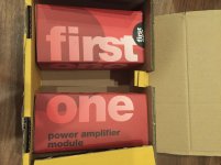
So, that's where I got to the idea of some minature BMRs playing at upper mid to HF. An idea not too much different than Linkwitz does in his recent dipole speakers or that Audiokinesis (Duke LeJeune) does with his "LCS" floor-mount ambience speakers. Duke's run full-range (I think), though. Mine will have the flexibility to add further DSP delay and time diffusion so that any energy that does arrive at the seat directly from the ambience drivers shouldn't disturb any of the clarity of the SmallSyns. It will take a few more amplifier channels, but really, decent class D amplification is so cheap and small now that amps aren't an issue.

If I really can get away with doing this only at HF (it's largely HF shimmer that seems to be lacking) then maybe I can use use open baffle for the BMRs -- have them firing both up and down, rather than waste the energy from the back of the drivers. If not, I've 3D printed some small wedge-shaped enclouser that could get them playing down at least to the mid-hundreds of Hz.

BMR drivers should come in sometime this week and I've got two of the wedge shaped enclosures ready so some first preview tests shouldn't be too far off.

(I've had some experience with Dolby surround, and simulated acoustic from back channels. It wasn't a great effect then, but I'm hoping this will do better. The surround channels had the problem of being too locate-able, at least when one was walking through the room, which for me spoils the illusion even after I'm seated. Hoping that stuffing the sound sources at the front and all behind the SmallSyns will avoid that).

Schematics for SANSUI AU-X417R?

Hello from Romania,
I just bought this amplifier (AU-X417R). It sound fine but I expect to improve the performances up to excellent by a full recap.
Unfortunately, I don't have the schematics or the service manual. No results with Google, seems to be a rare model.
Any idea where to find the schematics for this amplifier?
Thank you
Dan

PS
I found the schematic for AU-417 but is totally different compared with AU-X417R (another generation).

Newbie question about the Echo Link

Sorry but I'm asking something about the new Amazon Echo Link, in case you understand what it does. I read various reviews (see Review: The $199 Echo Link turns the fidelity up to 11 – TechCrunch for instance), pages on Amazon.com, and I'm still totally unclear about a basic question.

They say that the normal way to use the Echo Link is with an Echo Dot or an Echo Input. The 3.5mm analog outputs of these devices should be fed to the Echo Link, and the outputs of the Echo Link should be fed to my audio system. And this will give me a big improvement in audio quality.

How is this possible? I am fetching the streaming music bits into my Echo Dot or Echo Input. I'm converting those bits to analog using (I presume) a cheap mass-market DAC chip powered by rudimentary power supply circuits inside the Echo Dot. Then I'm pumping out this mediocre analog signal using a mediocre 3.5mm cable (where the signal returns of L and R are common) to the Echo Link. How can the Echo Link improve the quality of a mediocre analog input?

I've read dozens of Q&A about the device on Amazon.com and reviews, and this part is still unclear.

What am I missing?

Help with Roksan Caspian 5ch amp secondary voltages

Hello everyone!

Could someone help me with secondary voltages from a Roksan Caspian 5 Channel Amplifier?

I have 2 modules (like in the pic) from a friend but without transformer!

The pcb, already contains the bridge rectifier and two caps at 63v 10000uF.

I made a test with a 41-0-41 vac, it works, but I'm not sure if these voltages are safe

Thank you!

Attachments

  • fianco 3333.jpg
    fianco 3333.jpg
    97.3 KB · Views: 109
  • dietro.jpg
    dietro.jpg
    137.5 KB · Views: 117
  • dentro 55555555.jpg
    dentro 55555555.jpg
    149.3 KB · Views: 125

Help reparing Luxman L-113A

I am attenpting to repair the Luxman A-113A but my knowledge are somehow limited.

The problem is the left channel distorts. when I tried to bias the left channel the current was going up and down like crazy never getting a constant value.
I start measuring some values according to the service manual and notice the NPN driver was mad hot. measuring the base I get 0,8v and in the service manual points to 1,2v. I tried to replace the transistors already but the behave keeps beeing the same.


can you give me any tips here to measure next and identify the cause?

Attachments

  • L-113A.png
    L-113A.png
    463.6 KB · Views: 261

My DIY UcD amp from the junk box

Hi...
I'm proud to present my first UcD amp circuit.
All components come from the junk box (!) Yes, no money for this amplifier, no smd, no ic, no gold plated connectors, no strange japanese transistors.... on two homemade printed boards: a pcb for modulator, a pcb for power stage, 68X35 mm each.
It's perfectly running at 20Vdc (single rail supply, output cap!) on a 2 ohm load, delivering a very very clean, bright and powerful sound.
I've built a second power stage, and I'm planning to modify the modulator to drive two power board in bridged mode (so I can get away this horrible output cap!)
It's based on classd4sure schematics (threads: http://www.diyaudio.com/forums/showthread.php?s=&threadid=40307&highlight= ; http://www.diyaudio.com/forums/showthread.php?threadid=55385 ) (thanks to Chris, Bruno,etc. ), and on the big know-how of the people in this forum (thanks to all)!
Some data:
power Mosfets: IRF540
transistors in modulator: BC557 and BC237
transistors in power stage: all BC337 + 2SD478 (from the deepest and darkest place of my junk box) for stabilized voltage in gate drivers
all diodes: 1N4148, no schottky diodes!
output filter: 28 turns of 0.6mm2 enamel wire, on a ferrite bead... (about 22 microHenry), and 1microF cap
final output cap: a 30 years old, 1000 microF german electrolytic... last attempt to use it in a circuit!
This is the most simple and funny amplifier I have built in 15 years...
😀

Attachments

  • img_0090.jpg
    img_0090.jpg
    44.8 KB · Views: 3,189

3 Way Speakers Without Crossovers

I have built a triamp and currently use two pairs of Kef Coda 7 speakers wired for biamp so I only use the base speakers in one of the pairs.
This is temporary as I do not need any crossovers.
Although the sound is very good I would like to build a pair of cabinets/speakers without any crossovers.
I have never built any speakers and have only ever used the Kef's from new (my son had one set and I had the others).
I don't wish to spend large amounts of money as this would be the first attempt and I know from experience with the triamp that a few failures might be needed before success.
I am after some advice on what to use.
I have been recommended to try Scanspeak speakers but I have non experience of them.
I also am thinking whether it might be easier to build separate cabinets for the base speakers only with a combined cabinet for the tweeter and midrange.
I would be happy to achieve at least the same quality I get at the moment but if there could be an improvement that would be better.
I listen to my system most days; it does sound great and I keep thinking how on earth did I manage to build the triamp (took me about 5 years)

Mono Blocks possibly AEM 6000 diy kit

i have come across these beast's .

they both fully work , they have a form of a soft start on the back in a form of two power switches and a push button .

can anybody shed anymore light on the specs of these monsters they weight about 28 kg each

as. you can see one amp got damage but i managed to bend it all back

Attachments

  • WhatsApp Image 2020-03-26 at 18.21.57.jpeg
    WhatsApp Image 2020-03-26 at 18.21.57.jpeg
    195.6 KB · Views: 164
  • WhatsApp Image 2020-03-26 at 18.21.50.jpeg
    WhatsApp Image 2020-03-26 at 18.21.50.jpeg
    171.7 KB · Views: 162
  • WhatsApp Image 2020-03-26 at 21.12.42.jpeg
    WhatsApp Image 2020-03-26 at 21.12.42.jpeg
    166.5 KB · Views: 158
  • WhatsApp Image 2020-03-26 at 21.15.31.jpeg
    WhatsApp Image 2020-03-26 at 21.15.31.jpeg
    234.1 KB · Views: 162
  • WhatsApp Video 2020-03-27 at 12.51.18.mp4
    2.7 MB

Transformer Input/Output PCB design for First Watt PSU - Any good?

Hello, I'm here to put my head in the lion's mouth 😀.

I'm configuring a new power supply for an upcoming First Watt clone build, and this time I'd like to experiment a little more with the power section. The plan is to forgo the use of the DIYaudio Universal PSU board and opt for large screw-terminal capacitors in a CLC filter.

While trying to determine a suitable way to mount the rectifers and other components I wondered if I couldn't design a circuit board myself that would sit in-between the transformer and CLC filter. The PCB would mimic the function of the diode boards from the DIYAudio PCB, but instead use monolithic rectifer blocks and include additonal components not specified in the regular First Watt PSU design.

This is what I came up with:

93vkRf0.png


The middle section is for 240V AC mains input with provision for one or two thermistors on the live wire for the regular FW-style of inrush current protection, then exits to the primary winding of the transformer. This version also places the 3300pF line filter cap on the board before the thermistors, however I wonder if that be better situated near the main power switch instead.

Flanking the AC input section are the two output sections for the secondary windings. They are designed to incorporate a snubber, plus space for a fuse holder if fusing the secondary is desired. The rectifier blocks are the GPBC-W type with the through-hole leads, hopefully with ample clearance around them for heatsink attachment.

The question: Is this viable, or just rubbish? Opinions or suggestions gratefully received.

Original First Watt PSU, and preliminary new PSU design attached (*asterisks=optional).

Attachments

  • F5PSUschematic.jpg
    F5PSUschematic.jpg
    66.2 KB · Views: 346
  • psu.png
    psu.png
    76.2 KB · Views: 361

How do you guys make a horn contour list for CAD?

Hi guys!
I’ve been a background member of the forum for a little while now, and I have to say, I’ve learned some really useful things and had some long standing questions answered, so a big thanks to all for the posts!
I’m not sure on the best way to describe what I’m trying to ask, but I’m currently modelling a 8” hyperbolic mid horn for pa use, and I’m looking for some tips on how to translate the measurements in Hornresp into something I am able to make a 3D render of in Sketchup, so that I’m able to follow the correct flare rate etc. I’m aware that AJHorn has a feature to export a contour list which will give cross sectional areas for given points in the horn, but I don’t have AJHorn so unable to use this.
Also, unlike some other beginners, I’m totally open to suggestions from you guys if anyone thinks I should use a different horn topology to hyperbolic, any suggestions are greatly appreciated...
thanks!🙂

Passive filter help please

Hi team, I have an bi amped horn system that I’d like to tweak a little. The mid horn has a passive hi pass filter that I’d like to do away with, looking to install the hi pass on the input of the mid-range amp.

The passive filter is a 2nd order and this combined with the horn roll off makes for a very step slope. Not 100% sure of the exact filter frequency so I’ll need to do some trials but its around 450hz.
Is there anyone out there that is willing to help with the numbers for a passive hi pass filter driving 100k ohms? I can build anything but fall down on the design skills, yes I know this is one of the easiest circuits but what I’ve tried so far hasn’t worked as planned…..

I've looked into this a few times but never got it sorted so time to try again.

Cheers Dave

Request Peer review of crossover

I am making a pair of small 2 way speakers for my basement workshop. I would like some feedback on my crossover design. It has been 18 years since I designed a passive crossover, and a lot of measurement and simulation technology has changed in that time. Best Practices have changed as well. So I am asking for opinions, thoughts, and advice before I order the parts for the passive crossovers.

Background


I am reusing the Vifa D25AG35 tweeters I pulled from my old speakers. Although they are 28 years old and have seen almost daily use, these tweeters still have the same frequency response and impedance curve as when they were new. Harmonic distortion is very good even by today’s standards.

These tweeters always worked so well with a polymer cone driver (Vifa P13WH in the old speakers). My basement can experience big seasonal changes in humidity, so I wanted to stick with poly cone drivers. I have had good experience with SB Acoustics SB17 series drivers, so I chose the SB17MFC35-8. This will be a sealed box system.

These speakers will be located on a large 8 ft x 3 ft work bench, with the speakers pushed back against a concrete wall. So they will be at the corner interface of a vertical concrete wall and a large flat wood surface. I am assuming I will need little to no baffle step correction, and this is confirmed by plots of total room response compared to ground plane response.
The box is 12.6 liter internal volume, not accounting for the volume of bracing and driver magnets. External dimensions are 13.5 inches tall, 8.25 inches wide, 11.75 inches deep. Internal dimensions are 12 inches tall, 6.75 inches wide, 9.5 inches deep. Wall thickness is 0.75 inch, baffle thickness is 1.5 inch. The sides and top edge have been beveled with a 45 degree angle to a depth of 0.75 inch. I do not plan to apply a finish to these speakers at this time.

Another reason for this project is I wanted to explore various ideas for constructing cabinets more efficiently. Some of those ideas worked out well, others not so much…

Attachments

  • 20200619_182019_HDR.jpg
    20200619_182019_HDR.jpg
    328.5 KB · Views: 660
  • 20200618_162149.jpg
    20200618_162149.jpg
    481.1 KB · Views: 339
  • 20200618_162228.jpg
    20200618_162228.jpg
    256.6 KB · Views: 373

Active volume control with 0dB of gain?

I don't know if this is the correct place (I didn't found a place for pre-amps). A few days ago I started a thread asking about a passive volume control, but thinking well I guess that maybe this is not the ideal solution for my case...

I have a great pre-amplifier which only thing that bugs me is the sliding control that won't allow me a smooth operation. To make things still "better" it doesn't have a separate balance control, instead it has TWO sliding controls for volume (left and right).

zozLKxa.jpg


Years ago when I had an identical pre-amp to this one the solution I found was to buy a second pre-amp (with a rotating volume control) and put it in series with the first pre-amp. Beside to have a lot of inputs available I left the sliding pre-amp at the maximum volume (with the -20dB button pushed) and controlled the volume in the rotating pre-amp.

I was about to do it again but I know that this is not the ideal situation because having a pre-amp pushing signal into another turns easier to induct distortion. Also I was thinking and maybe the passive control is not a good idea either because there is impedance issues and it may cause noise and also the high frequencies to be cut specially in low volumes.

From my very small knowledge in electronics I am realizing that maybe the ideal would be an active volume control but with 0dB of gain to avoid distortions.

Said that, there is someone that could point me a good (and yet as simple as possible) circuit to do this and that I could try to assemble myself in home?

I am opened to other suggestions.

Thanks a lot!

🙂

High level loop through subwoofer amp

TLDR
What premade boards can I buy to power an active subwoofer, provide volume and crossfade controls, and high level input/outputs

Hello,
I'm looking for information on adding high level loop through to a subwoofer amp.

I was given an older busted Boston Acoustics subwoofer and thought I'd take out the electronics and put in a premade class d amp board and subwoofer control unit.

Having high level input and output would significantly improve a system I have floating around the house and I can't seem to nail down the right search terms for the results I'm looking for.

Thanks in advance.

Ps: I was going to approximately follow directions I found in this video YouTube

He talks about using:
100 watt Amp Board TDA7293
Cross over board NE5532

Though I may need to find something with more power became it used to be a 220w active sub.

Good Commercial Dome + Waveguide Solutions Available For The DIYer 2020

Hi DIYA!

Well, the topic really says it all, I'm interested in seeing what successful and really nice sounding dome and Waveguide solutions that I might have missed, that I might use for future projects. So, what easily accessible solutions is out there?

I know about severel of the more known ones, and between those I think I would go with the Seas DXT, but there may very well be some that I haven't read about that might be a better sounding and measuring one?

I have read mostly positive comments about the DXT, but I haven't heard it and I do think I prefer a soft dome over a hard dome, not really sure on that as I have heard both sounding really nice.

Almost every single speaker I have own in my life have been using a waveguide, and it seems to really only have benefits in my limited knowledge.

The intended use would be as usual, and probably in a series of speakers I have been planning and thinking about. I'm doing this mostly because I want a deeper understanding in what makes a speaker sound like it does and what knowledge and decisions that lies behind creating a nice sounding speaker. These speakers are probably going to be a series of similar speakers from a small 2-way studio monitor thru a 3-way middle sized floorstander to a large 4-way, using the same tweeter and Waveguide, and probably the same midrange in the larger ones. All eventually passive ones, although a active solution at least for the smaller ones are possible thru the creation of the speakers.

So I am most probably looking for a quite variable tweeter and Waveguide combination, with a possible crossover between 2-3khz, and should ideally be able to mate well to both a 4" and a 6,5", if possible, with a lower/higher crossover.

I also want it to have somewhat small outer circumference, as I do intend to be trying both MT and MTM arrangement, and as such want to try and keep the C-C distance somewhat reasonable. So larger ones than 6,5"- 8" is probably the limit, I guess, as I don't plan on using anything larger than 6,5" as a compliment to the tweeter. I do think I am leaning on a 4 Ohm solution, as I do want to try MTM and MT solutions.

I preferably want a combination that is known for a nice sounding sound, and something that is easily accessible over here in Europe, preferably also in USA.

So guys, what out there that sound nice and is easily accessible? Anything new? What about the SB Acoustics new one? How does the Visaton solutions hold up?

It doesn't have to be a complete package as the DXT is, but it should as mentioned be easily accessible and hopefully so for some years ahead, although that is really hard to know in beforehand.

Thank you for your help in beforehand!

🙂

FS: Hypex AS2.100D w/

Have 2 pairs for sale. Each pair comes with the optional remote and touch panel.

Totalling $660+ in retail, I'd like USD350 per pair excluding shipping and paypal fees.

Do note they ship out from Singapore.

More info here
https://www.madisoundspeakerstore.c...sp-active-2-way-amplifier-with-digital-input/
https://www.madisoundspeakerstore.com/hypex-amplifiers/hypex-touchpad-for-as2.100-amplifiers/
https://www.madisoundspeakerstore.com/hypex-amplifiers/hypex-remote-control-for-as2.100/

Erno Borbely super shunt regulator

I purchased 320 Phono and EB906/255 super shunt regulator from Erno Borbely a few years ago. Last year, I changed the regulator to Dexa and put aside the 255. Recently, I wish to use it again for another diy kit but I could not find the 255 circuit diagram again. The new diy kit uses only 20mA that the current setting at 240mA would make the power transistor red hot.

I remember there is a formula to calculate the resistor value but I can't find it. Can anyone give me the formula, or the value for 30mA or Erno's email addres (I wonder if he still reply email today).

60-300hz other than horn loading

I need to fill the gap between my sealed subs and midrange horns.
60-300hz would be the range I need with smooth top end roll off.
The 60hz horn is big (long) and I am considering other loading option that are the next best where high efficiency and low distortion is priority.

Here's a plan but not sure if it's good for my range -- anyone know this?
not_horn.jpg

My 2nd find:
horn loaded 7th order banspass:
www.renkusheinz-sound.ru/pdf_datasheets/CE3TLOK_data.PDF

Would appreciate any recommendations from someone who has heard good midbass horns and experience other (close 2nd) loadings....
thanks
Herman

I'm hesitate between those two line preamp circuits

Hello

I'm hesitate between those two line preamp circuits, both are old diy circuit done years ago that I have just modified with Ltspice.

Any suggestions, ideas ?

Thank

Bye

Gaetan

Attachments

  • Jfet preamp with_gains-pf5102-ver3-FINAL-with feedback-mai 2020-image.GIF
    Jfet preamp with_gains-pf5102-ver3-FINAL-with feedback-mai 2020-image.GIF
    25.5 KB · Views: 213
  • my fet preamp-new version image.GIF
    my fet preamp-new version image.GIF
    33 KB · Views: 219

Ballast Tubes as a CCS

Can a ballast tube be used as a CCS in an amp, say rather than a SS CCS used on the plate rather than a choke or a resistor? Maybe as a Cathode bias? There seems to be a large list of available tubes, although finding one to meet an exact requirement would likely be difficult. What would be the result it using one if it can be used. These were kind of the LEDs of the day? I have never seen such a thing, but ......

4-way mid bins?

So we got our subs 20-90hz
And we got our kick bins 90-400hz (could cut down to 200-250 but they are flat to 400hz)


Obviously I'd want to use a horn for my highs somewhere between 1.8k-6k depending on the mid cabinet/driver used...

So what are people using for their mid bins?

Ideally I was thinking about hanging some multi-cell horn paths like some altecs or something..... But this means I would need some kind of mid bin in order to fill that gap between the kicks and the horn.

Anyone ever hear of any designs like this?

Or any suggestions for build types to optimize output of 400hz+ up to say 2khz?

Aikido/WCF headphone amp

I've been using my "Brute Force" mu follower amp for headphones for many years but I needed something that could drive lower impedance headphones. I found the Glassware schematic for the Aikido/WCF amp online so I decided to build it point-to-point. I've got it working now, it sounds great with my Grados. It uses the same (6SN7/6BX7) tubes as the old amp and I've configured it for 32 ohm operation.
But since it's optimized for 32 ohms, what happens if I plug in higher impedances? I have 4 headphones ranging from 32 to 320 ohms and I'd like to use them all.

Help with identification and some advice, please. Grace 707 arm / Cartridge

Hi All,

I haven't set up a TT in ages, and I'm sure that when I did it - it wasn't properly done. Establishing myself as a noob that just barely knows the terms surrounding TTs and components. 😀

Onto it...

My brother has a Denon DP3000 table with a Grace 707 arm and an as-yet unidentified cartridge / stylus.

He's the 2nd owner and has had it for 30ish years. He thinks he got it in 89.

Lately, he's said that it just doesn't sound quite "right". I'm hoping I can help him out a bit. He's gone to a local person (purportedly familiar with the arm etc.) to have the relevant physical settings adjusted.

No particular improvement to his ears. However, the person doing the alignment etc. (to the best of my knowledge) did not check the stylus or cartridge condition. I also don't know if the phono stage was ever set up properly for the cartridge. However, I assume it was. The sound was marvelous years ago to my ears.

Set up -

Stylus and Cartridge - Unidentified. Pics attached.
Arm - Grace 707
Table - Denon DP3000
Phono Stage - Forte FP 1
Pre - Forte 44
Amp - Forte 4
Speakers - Vandersteen 2C

First - could anyone help in identifying the cartridge? I tried to get a look at the back and bottom to no avail. I did not see any markings. Since he just paid to have it all re-done, I'd hate to loosen it and take it off.

Second - Any advice re: simple places to look and/or check to see if the stylus / cartridge is performing "properly"? I read an article re: stylus wear. That may require a more skilled person for evaluation than I. It plays music, but I do agree after all these years that some of the "life" has gone out of the music. With CDs etc. and other sources, the chain is just fine. So, I'm narrowing the search down to components directly related to the turntable / phono stage.

Third - Do phono pres potentially need any loving care? I had the power amplifier re-capped about 6 or 7 years ago due to an electrolytic failure.

I'd truly appreciate any insight. It's a lovely system, but the record collection is collecting dust at the moment.

:cheers:

Attachments

  • IMG_2103.jpg
    IMG_2103.jpg
    506.7 KB · Views: 89
  • IMG_2104.jpg
    IMG_2104.jpg
    424.6 KB · Views: 92
  • IMG_2105.jpg
    IMG_2105.jpg
    589.2 KB · Views: 89

Bluetooth speaker stereo - way is it a problem?

After looking around it seems like connecting two Bluetooth speaker to one source and have them play stereo is a problem and not common.
Just connecting two speakers (booth playing the same) seems to be not always possible?

I found this old article: Tempow turns your dumb Bluetooth speakers into a connected sound system – TechCrunch
And i was on that Tempow site: Tempow | Enabling the next generation of Bluetooth Audio

Looks like some proprietary stuff that needs to be build into the device.
Not just software you can use everywhere...

I did see there are speakers out there that can do it. But you always need special software from that company and it does not work with all there speakers.

I wonder why its so complicated. I mean Bluetooth headphones play stereo - or not?

First One Amplifier Module v 1.2

I have here 2 First One amplifier modules v 1.2. If you look closely at the photos you'll see one of the capacitors has a bulging top. I did something during set up and I would only be guessing if I listed a reason for this. I just don't remember. I just ordered 2 more modules from "lazy Cat" and finished the amp.

So 1 module is good, basically unused the other consider not working.

$50 plus shipping.

Attachments

  • fullsizeoutput_139.jpg
    fullsizeoutput_139.jpg
    603 KB · Views: 312
  • IMG_4542.jpg
    IMG_4542.jpg
    749.2 KB · Views: 335
  • IMG_4543.jpg
    IMG_4543.jpg
    569.2 KB · Views: 310
  • IMG_4544.jpg
    IMG_4544.jpg
    618.8 KB · Views: 314

Sundown scv6000

I have a sundown scv6000d that had several mosfets blown in the power supply. Replaced all bad parts and I have the amp up and running, but one of the banks in the power supply has a slight deviation in the square wave as compared to the other three.
Is this a problem? Picture A is the 3 banks picture, B is the one in question. thanks for any help

Attachments

  • A.jpg
    A.jpg
    976.7 KB · Views: 100
  • B (1).jpg
    B (1).jpg
    977.6 KB · Views: 94

Building a better streamer than Node 2i

Need help 🙂
Please, if you're the "bits are bits" kind of guy, I would ask that you refrain from commenting, as by questions are based on the opposite attitude.

A couple of weeks ago I came to the conclusion that I wished to upgrade my Bluesound Node 2 (not 2i) streamer in 2020, and I began contemplating if the upgrade should be Raspbery Pi (or other SMC) based.

This is my baseline:
Bluesound Node 2 (connected with a coaxial cable)
NAD C510 DAC
Dual mono Pascal L-Pro2s amplifiers
Dynaudio Contour 60

Originally I wanted to switch my streamer out with a Node 2i, as it has been apraised for the improvement in sound quality compared to the Node 2 that I own. So my goal is to either match the SQ of the Node 2i or exceed it. I do wish to keep my external DAC, which does include both coax and USB input.

So for the last week I have been looking into SBC's and HAT's that be interesting, but I lack a comparison of the majority of them, and especially comparison between "tweaked" SBC's and RPi with hat.

These are some of the SBC's I've seen:
- Raspberry Pi 4
- Asus Tinker Board S
- Allo USBridge Signature
- Khadas VIM3

HAT's:
- HIFIBERRY DIGI+ PRO
- IAN CANADA TRANSPORTPI
- I2SoverUSB v.III
- Allo DigiOne Signature
- Allo DigiOne
- JustBoom Digi HAT

What should I go for?
Seing that my DAC accepts USB input, would it make sense to use an audio improved SBC as the Allo USBridge and just use the USB port, of would I get a better result using a RPi 4 with a hat and using coax, or even a combination of improved SBC and HAT? How do I get the best possible result with what is possible to buy and assemble?

All input and pointers are very much appreciated, just keep in mind that the total cost of electronics needs to a maximum of a $700. 🙂

Preamp power supply

Hi, I am going to build +-15/ +5 v power supply and post my schematic here for review.
The +5v is for arduino MCU controler


It is basically CRC filter and a voltage regulator.

Any suggestions/ comments about topology and parts value is appreciated.
F.ex.
- The electrolyte cap values in CRC - way too big before voltage regulator?
- The extra caps C111/112, C21/22
- Using one big polygon for DGND and AGND, instead of option for ground potential lift? I am schizophrenically afraid of ground loops...

Woofer choice for WHW configuration

July 9, 2020: This thread is evolving from selecting a Woofer for my WHW DIY project (selection is now closed - I've ordered four Peerless/Vifa/Tymphany NE315w-04's - they should be here by End of July, early August 2020.

The next phase will be to build and test the optimal enclosure for the woofers, since calculations show that a small 48L / 1.8 cu.ft enclosure is all that is needed for a sealed cabinet with F3 near 45 hz.
The quality I'm missing from my current speakers is that visceral thump from the kick-drum or fast Low Frequency transients (between 50 and 150 hz). I'm hoping these drivers can deliver that, so I will be paying attention to the enclosure to minimize vibration via damping and CLD techniques. I am also following several threads on cabinet construction to understand those concepts a bit better.

June 29th, 2020: See posts #38 and #54 for Sealed/Vented Box alignments and FR performance comparisons My current bias is to go sealed, due to the cabinet size requirements.

856564d1593442473-woofer-choice-whw-configuration-woofers-jpg


June 24th 2020: I'm looking for 12" woofer recommendations in the $100 to $250 range (each) I'm evaluating these options: (I'll be using 2 per cabinet)

1) SB Acoustics SB34NRX75-6 12" Woofer
2) Peerless SLS 830669 - 12" Woofer - Coated Paper Cone
3) Peavey pro 12
4) Dayton Audio RSS315HF-4 12" Reference HF Subwoofer 4 Ohm
5) Eclipse, W1238R 12" woofer
6) Peerless by Tymphany NE315W-04 12" Paper Cone NE Woofer 4 Ohm
7) Goldwood GW-12PC-8 12" Heavy Duty Woofer 8 Ohm


I'll be building a WHW with the Horn in the center similar to The Raptor ... a 10" MTM. One difference is that I would probably turn the horn vertical so that the horizontal dispersion angle is 40d and vertical dispersion is 60d, and I'd like to go with 12" woofers to get more slam and low end extension. (not sure about sealed or vented yet)

I recently received two 18 Sound XT1464 horns antwo SB65WBAC25s full range drivers (similar what was used here: A Bookshelf Multi-Way Point-Source Horn but I have room for a larger box. I think I'll use MiniDSP 4x10HD as a crossover, eq, and phase correction.

My Living Room is 13' wide, 24' deep and 9' tall. I'm usually sitting about 12' from the speakers which are toed-in near the corners of one end of the room. I currently have 2 B&W 640i as the mains, which are probably bouncing sound off the walls, roof and floor like crazy. (though I use the receiver's Audyssey Curve Editor to get a flat FR at the listening position - confirmed by REW).

Thanks - Six - Minneapolis.

New Method for Automated Polar Measurements... Feasability Question!

Hi all,

I am at the beginning of a long journey... building my first true (fully self-developed) DIY speaker project. I have built several kits before and have also developed a very small 2.1 system for my PC workspace several years ago. These projects were cheap, with little amount of labor and cost involved. This will change now: 3-way active with Hypex Fusion amps, professional neodymium drivers and quite a lot of sawdust is to be expected.

Since I have several promising drivers for each position to compare, a lot of measurements will have to be conducted. These will be fully polar in order to obtain directivity patterns for each of the options. Now, I am tinkering with an automated turn-table approach.

For gated IR measurements I can use a large garden. Putting the prototype cabinet on a speaker-stand like this:

K&M 21435 Boxenstander – Musikhaus Thomann

will yield roughly 2m distance from the lawn. There is also no other obstacle (buildings, trees etc.) in this 2m radius around the pole. This will lead to about 9ms before the first reflections will hit the microphone (assuming 1m meter distance between baffle and mic). Please correct me if I am mistaken!

Now, instead of rotating the cabinet in two meters height (quite a mechanical challange...) I propose rotating the microphone around the center pole with a rather lightweight turntable mounted underneath the cabinet-plattform.

Is this (acoustically) sensible approach? Any ideas and comments are highly welcome!

kind regards

Marantz 2330 - Seeking help debug P700 power amp burned resistors

hi all,

I upgraded and modified my Marantz 2330 :
- Replaced all electrolytic caps for Power supply P800, PE01, PH01, power amp P700
- Updated to film caps on the signal path and feedback path for tone preamp, and main power amp modules
- For Power supply P800 Updated to fast recovery diode (MUR1620CTG), H801, H802 to MJE15032G
- For main power amp P700, i replaced differential input pairs Q701, Q702, and Q703 to all KSC1845FTA with Q701 and Q702 matched hfe as closed to each other as possible

After all the mods & upgrades.
- I was able to observe a constant voltage of 35 Vdc of b/w J804 and J805 on P800. I noticed almost all of the new caps from P800 pwr supply are pretty warm to a bit hot the receiver is making music. Is it normal for PS caps to get warm to a bit hot with this high of power ? I upgraded the caps to all high temperature (105 C), low ripple, with higher voltage rating than original caps

- When adjusting bias current for both left and right power amps. I noticed 1 side of P700 is able to be adjusted to 13.5 mV and it stayed there after the amp is warmed up. The other side of P700 bias voltage is somehow jumps to 15 mV or 16 mV after it was settled at 13.5 mV as the other side. When it jumps to 15 mV, i readjust the trimpot to bring it back down to 13.5 mV, then the other side starts to slightly increase the bias. By the way, the P700 amp that has the jumping bias voltage is the one with the damaged and burned resistors/diode/transistors as explained below.

- After 2 days of music enjoyment, I smelled a funky smell and smoke coming out of the right channel of P700. This is the PA module that sit closed to power supply P800

Pulling both P700 boards out (left and right) with left was the one that sit closed by P800 board. I noticed
- R730, R732 resistors are complete toast (Please see photo)
- Q724 transistors are damaged with short from B to E
- Diode Q717 was burned. C720, C721 are burned (See photo)

Please see photo and schematic highlighted for the damage signal path.

Instead of replacing the damaged transistors, diodes, caps and resistors, I want to understand why it causes such behavior that leads to the damages for the R730, R732 paths all the way down to Q724, diode Q717

Can someone help me understand the circuit better (P700 schematic attached) ?What is the purpose of transistor Q724 ?
Does anyone know what the actual causes ? it only happens on 1 side of the P700 board. The other P700 board is fine and does not have any issues. I checked the each of the output power transistors and all of them are still alive and functional. Power supply still provide a constant 35V

I have a theory of C718 = 330pf is going bad and short circuit which allows DC current from bias transistor Q708 flow through B of Q724. Thus, it short ckt B to E of Q724 and burns R730 and R732 on its path. C718 does not look burned from visual inspection but I will remove it out of the PCB and check it.

Many thanks,
Tom

Attachments

  • IMG_8240.jpg
    IMG_8240.jpg
    527.9 KB · Views: 134
  • 2330_P700.png
    2330_P700.png
    868.9 KB · Views: 126
  • 2330_P800_PowerSupply.png
    2330_P800_PowerSupply.png
    446.3 KB · Views: 124

Old Celef 2 Ways - worth restoring?

They are Celef CF1 Cirrus. Made in the UK, they became Proac later on I believe.

They need new drivers and probably crossovers I would think. They are a sealed design it looks like, Made out of 10mm chipboard veneer. So I am guessing the cabinet construction is not all that great.

Thought maybe I could put some nice new drivers and crossovers and might have a little gem? Or am I wasting my money?

I can post all the dimensions if anyone wants to make any reccomendations.


Thanks.

Attachments

  • CF1- 1.jpg
    CF1- 1.jpg
    64.2 KB · Views: 64
  • CF1-3.jpg
    CF1-3.jpg
    96.1 KB · Views: 75
  • CF1-4.jpg
    CF1-4.jpg
    95.3 KB · Views: 69
Projects by fanatics, for fanatics
Get answers and advice for everyone wanting to learn the art of audio.
Join the Community
507,765
Members
7,887,489
Messages

Filter

Forum Statistics

Threads
406,178
Messages
7,887,489
Members
507,765
Latest member
aleminx