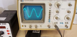
Repairing this reciever and the signal looks good on the scope until I connected a speaker at which point it becomes severely distorted. The scope shows almost a 35v ptop signal without speaker, with the speaker its more like 2v peak to peak. You can see the voltages sag on the driver transistors base and emitters. The collector stays fairly constant. I disconnected and check the finals and they are good. All driver transistors test good. Emitter resistors are good. Head scratcher... any advice? I know these are notorious for bad driver boards. One of them I rebuilt and the other was still good but both boards act the same.
Yes the driver board has a heat problem ---well known to Sansui at the time even in your version 2 and into the early versions of the 5000x .
F1040 or F1020-1 boards faulty --upgrade is F6013.
I take it we are talking about "sag " in the signal NOT in the DC voltages -----correct ??
If not and its a DC voltage "sag " then its still a biasing problem or loss/lack of gain while under load which would point to the type of BJT,s installed .
If so I would check the biasing for a start to see if there is a current drop (BJT,s current driven ).
The later 5000x seems to command a good price.
This is all conjecture as I don't have the circuit so could be wrong but you said you tested all the BJT,s .
Thank you for the reply. Yes the boards have a ton of history and a well documented Sansui recall. The 5000X mostly received the upgraded boards so likely why it is the more valuable option. I have the F-1040-1 boards. When it came to me one of them was blown and made no sound, the other channel still passed sound but sounded bad. I rebuilt the blown board with all new caps, 3 new transistors and modded the diode assembly. The older board still has original transistors and diodes for now but I went ahead and recapped it as well. Both boards now work bout sound poor and anything past a 2 on the volume gives me heavy distortion with the signal sometimes cutting out all together. I went ahead and recapped the EQ amp as well but no change. This is about the point I noticed that the signal looks normal until I connect a speaker. I subbed in new PS caps and speaker caps but it didn't help. Sansui doesn't really give you many voltages on the schematic and the ones that are there don't all make sense to me. Both boards were biased per the procedures but to your point, I could still have a bias issue elsewhere. Confirm that I am seeing large DCV drops on all driver transistors on Base and Emitter and about 1.5 v on the collector with the speaker connected as this results in what was a 35v peak to peak signal down to a distorted 2v peak to peak signal.
Here are links to the schematic. I'll try to get a few scope pics after while and some transistor voltages to help everyone see what is going on. Any further help is appreciated.
http://akdatabase.org/AKview/albums/userpics/10007/Sansui 5000A Schematic.pdf
http://akdatabase.org/AKview/albums/userpics/10007/Sansui 5000 Service Manual.pdf
Last edited:
I found the scope at an estate sale about 5 years ago. I've never had to work on it and it just keeps on ticking.
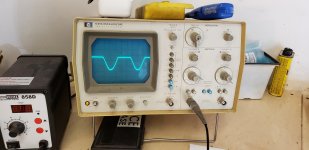
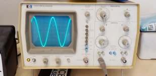
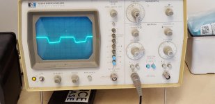
I have swapped out the output transistors a few times with some pulls and same result, I guess there is a chance they are all injured but still measure okay. Here are some better shots of the waveform, notice the massive reduction in gain overall as well. One thing I can try is swapping the output transistors to see if the issue follows the transistor. I may try that since they are socketed.
I have swapped out the output transistors a few times with some pulls and same result, I guess there is a chance they are all injured but still measure okay. Here are some better shots of the waveform, notice the massive reduction in gain overall as well. One thing I can try is swapping the output transistors to see if the issue follows the transistor. I may try that since they are socketed.
Attachments
Last edited:
Switches have all been cleaned and the caps have been changed. PS caps were swapped but didn't make a difference. I just experimented by disconnecting the base of the output transistors one by one to see which channel was bad and it made no difference what so ever. In fact both of the bases are disconnected right now and the waveform hasn't changed one bit, almost like the outputs aren't doing a thing. I may hook one of them up through my DMM and check for current draw. Emitter resistors are good. Strange one..
Will do. I checked the base of one of the transistors and it isn't getting a signal so I have something wrong down the line on that side. It is an easy amplifier and I think that is why I am getting frustrated but thank you for resetting my thinking. Often times you stare at something so long you miss the obvious.
You have an interesting protection scheme. By the voltage from the base of the output transistor, the thyristor opens. The supply voltage of the input stage is reduced. The input signal is limited.
Perhaps you see protection triggering. There may be low load impedance (loudspeaker).
Perhaps you see protection triggering. There may be low load impedance (loudspeaker).
I considered that as well. The yellow wire from the protector board supplies a 25V rail to the F-1029 board and cutting this wire kills the signal. I actually have the wire coming from the 1040-1 (white) to the protector disconnected to eliminate that variable although it made no difference. I also considered that the protector bulb was blown and I was in protect but didn't know it. Well, I found a procedure to align the protector and the bulb and SCR work as designed. I think I will try to fed the 1040 board a signal from my audio generator and see how it does although I am not expecting much change. The only thing I know to do at this point is to start changing transistors even though they check okay and see if it comes back to life.
The way I understand the protect circuit is that when the 1040 board pulls heavy current (approx 8.5v PP) it forward biases one of the 1N60's which in turn turns on the gate of the SCR. The SCR turns on some transistors and then switches the 25v feed from through the lamp to the preamp to ground shutting down the audio and turning on the protect lamp. If you have the upgraded F6013 boards the protector can be disconnected all together.
Last edited:
- Status
- This old topic is closed. If you want to reopen this topic, contact a moderator using the "Report Post" button.
- Home
- Amplifiers
- Solid State
- Sansui 5000a help