Protection limits the power supply to the preamplifier (dot D).
This may cause visible distortion. The trigger level is adjusted by trimmers. You can set it to a minimum, and then set the face value.
This may cause visible distortion. The trigger level is adjusted by trimmers. You can set it to a minimum, and then set the face value.
They were set to minimum when I got it plus yesterday I hooked up my signal generator directly to the driver board and I got the same distorted signal. I don't think the protector is the issue and it appears to me it can be bypassed by connecting point D to the lamp. I threw up my hands yesterday, removed the board and started removing transistors and measuring them with my sencore TF-17a. All of them tested fine except the 2SC485 showed leakage (7uA). Could be it?
I may move over to the other driver board today and see if it gives me any different results.
I may move over to the other driver board today and see if it gives me any different results.
Last edited:
So I have done that and actually changed a few that were out of tolerance. I swapped over to the other driver board this morning and have almost exactly the same results and this board has all brand new transistors in it minus the to66 drivers (which test fine). I removed the speaker fuse and threw my ma meter across it. I wanted to see what kind of current this thing was drawing when I hook up the speaker. No speaker I am at 15ma, with speaker I am 110ma max. That's it....100ma is all the power supply is giving me. I am not sure how to interpret that. Bad PS diodes, or maybe a bad transformer? How can I safely test the transformer current draw? Could it be a simple as a high wattage resistor, an amp meter and variac? Can't say I have ever done this before.
The amplifier should be tested under load with a 20 watt/8 ohm ) resistor( at least 20 watt ) across the output -- no load isn't going to do anything .
If you are talking of the power supply by itself then that too must be under a load .
Do NOT leave it under a continuous load when you start testing only do that if everything is testing okay.
Faulty diodes would show up as other faults as well .
If you are talking of the power supply by itself then that too must be under a load .
Do NOT leave it under a continuous load when you start testing only do that if everything is testing okay.
Faulty diodes would show up as other faults as well .
Last edited:
So I have done that and actually changed a few that were out of tolerance. I swapped over to the other driver board this morning and have almost exactly the same results and this board has all brand new transistors in it minus the to66 drivers (which test fine). I removed the speaker fuse and threw my ma meter across it. I wanted to see what kind of current this thing was drawing when I hook up the speaker. No speaker I am at 15ma, with speaker I am 110ma max. That's it....100ma is all the power supply is giving me. I am not sure how to interpret that. Bad PS diodes, or maybe a bad transformer? How can I safely test the transformer current draw? Could it be a simple as a high wattage resistor, an amp meter and variac? Can't say I have ever done this before.
AC or DC current?
After the capacitor to the speaker?
You can check the incandescent lamp 100 watts.
Check the pinout of newly installed transistors.
Last edited:
I was testing with an 8ohm 20w resistor on the speaker and checking DC mA across the speaker fuse witch is connected to the Power supply.
1) Start verification with PSU. Measure all voltages DC in accordance with the diagram. Check the voltage of 76.5 V under load (50-100 ohm or 100 W lamp) with the 4 A fuse removed.
2) Check with the tester the transitions of all transistors, the pinout and resistors (with the power off).
3) Instead of fuse 4 a, turn on the terminating resistor or lamp. Remove the voltage DC map on all transistors relative to ground. The output transistor collectors are disabled. Check the operation of the trim tabs. Compare channel results.
4) Apply a generator signal of 50-100 mv 1-2 kHz to the input of the amplifier board directly, bypassing the preamp. Monitor the output signal a) without load; b) with a load of 100 ohms.
5) If OK, connect the collectors of the output transistors, install.
Repeat 4) with the installed fuses 4a and a load of 8 ohms at the output of the amplifier capacitor.
6) Check the operation of the protection (reduced preamp power).
7) Think)))
First off, thanks for staying with me on this. Let me get some clarifications on a few of these.
1) Are you saying placing a 200 ohm resistor in place of the fuse and then check if I still get 76.5 volts? I don't have a lamp I can install in such a manner. I have a dim bulb and a variac if your concern is protection or shorts.
2) this has been done and but will do it again.
3) Are you once again installing a resistor in place of the fuse? Not sure what you mean by "DC map", I assume you mean desolder the collector pins to disconnect them from the DC supply or maybe you mean to desolder the emitter resistors? I also assume the "trim tabs" are the trimmer pots? These have been verified as good during the biasing procedure as I can see the voltages move around with my meter.
4) I've done this as well but not with a 100ohm load. Are you saying a 100ohm "Speaker" load instead of 8ohm?
My apologies as I am not familiar with some the lingo.
Current limit for safety.
Temporarily disable high-power transistor collectors. The amplifier can operate at a load of 100 ohms.
Measure the voltage on the e-b-с of each transistor relative to the ground. Record values for both channels.
Have you measured the resistance between (C) and the speaker outputs? Must be 0.
Temporarily disable high-power transistor collectors. The amplifier can operate at a load of 100 ohms.
Measure the voltage on the e-b-с of each transistor relative to the ground. Record values for both channels.
Have you measured the resistance between (C) and the speaker outputs? Must be 0.
Last edited:
Got it and just a note, I don't work on this stuff unless it is plugged into my dim bulb or my variac/isolation transformer.
I only have one driver board installed currently but can get you what you are asking for that one board. The other leads for the other boards are taped off and the fuse removed. I'm not sure if I have a 100ohm high wattage resistor but I know I have a 220 ohm. Standby.
I only have one driver board installed currently but can get you what you are asking for that one board. The other leads for the other boards are taped off and the fuse removed. I'm not sure if I have a 100ohm high wattage resistor but I know I have a 220 ohm. Standby.
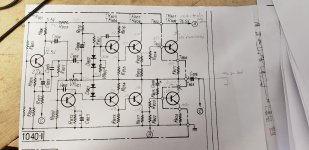
Setup: 200mv signal input into auxiliary input. Speaker load is 120ohms (found another resistor). Output transistor collectors are desoldered, the base and emitters are still connected. Protector and negative feedback loop wires are disconnected. Volume adjusted to just before breakup. Voltages taken on all driver board transistors (see pic).
Attachments
"Have you measured the resistance between (C) and the speaker outputs? Must be 0."
I assume (C) is collector? If so, then one of the collectors goes to the PSU and the other goes through the speaker capacitor. Maybe I am missing something but the resistance will not be zero to the speaker terminals as it is quasi and capacitor coupled.
I assume (C) is collector? If so, then one of the collectors goes to the PSU and the other goes through the speaker capacitor. Maybe I am missing something but the resistance will not be zero to the speaker terminals as it is quasi and capacitor coupled.
"Have you measured the resistance between (C) and the speaker outputs? Must be 0."
I assume (C) is collector? If so, then one of the collectors goes to the PSU and the other goes through the speaker capacitor. Maybe I am missing something but the resistance will not be zero to the speaker terminals as it is quasi and capacitor coupled.
0 ohm - Between point (С) on the circuit and speaker terminal, taking into account the position of the output switch.
Setup: 200mv signal input into auxiliary input. Speaker load is 120ohms (found another resistor). Output transistor collectors are desoldered, the base and emitters are still connected. Protector and negative feedback loop wires are disconnected. Volume adjusted to just before breakup. Voltages taken on all driver board transistors (see pic).
The signal is fed to the Tr802 base through an additional capacitor as C804.
Voltages are similar to normal.
Tr804, Tr805 is something wrong.
Last edited:
I thought I saw a node and missing base voltage there at R825 on theschematic but it passes through. I have 1 ohm from point C (negative feedback) to the speaker terminal I am testing with. Not sure how I get 35V on a disconnected collector on TR807 and also not sure about 35V on the base there either..
- Home
- Amplifiers
- Solid State
- Sansui 5000a help