Understanding midrange driver output capability

I am trying to choose the right midrange driver for my project. The driver will have to be capable of at least 110db/1m peaks Without audible distortion or compression. The passband will be around 300Hz to 2500Hz with up to 6th order filters.

For example the SB12MNRX2 will in theory be able to do this driven with around 100w, and crossed the 300 Hz the excursion shouldn't be an issue. Max Power handling is 100w, so that should also be okay.

Can I be confident that this driver will do the trick, or is it something else I should consider?

preamp grounding question

So on a preamp when you mount the pot to the faceplate, whichs how it is most of the time, the chassis has to become a ground plane inevitably because the casing of the pot has to be grounded also.

My question is would it be better to somehow isolate the pot from the chassis (i can think of several examples) so that the chassis can be an earth shield instead?

2nd question regarding the pot's casing being grounded- for a true mono mono psu how would this be configured if i want the ground between L and R completely separate? The pot's casing is usually one piece.

CD Player +/- PSU odd sized filter caps.

Looked fo this one and can't find it.


So, looking a the circuit diagrams of a few CD players I've found some, have differing sized filter caps after the rectifier diodes and before the regulators in the +/- supplies.


Can anyone shed any light on this, i.e. why a manufacturer would use two different sizes?


My guess is this is mostly because of rail loading but also to keep costs down.


Attached are the PSUs from two cd players that are very similar:
The DCD620 has one 2200µF cap on each rail.
The DCD820 has the same 2200µF cap on the negative rail but a 3300µF on the positive rail. The DCD820 has four additional +5v IC's one for volume control and three for de-glitch (sample and hold)

Attachments

  • DCD620 PSU.jpg
    DCD620 PSU.jpg
    175.4 KB · Views: 82
  • DCD820 psu.jpg
    DCD820 psu.jpg
    647.3 KB · Views: 81

SMPS drops to lower voltage

Wasn't sure where to post this but here goes. I'm trying to use an SMPS made for tube applications. Specs-
(Input voltage: 12VDC
Output high voltage: 150V-420VDC, 1.25V-12V DC filament voltage regulator is adjustable. (Chip voltage regulation, there is a little pressure drop.)
When I connect to preamp,(load), it drops to ~170VDC after being set to output 240VDC. The low voltage 6.3VDC is fine. Attached is pictures of setup:
I'm using an 12VDC/800mA wall wart for SMPS input. Have never used an SMPS before so hoping for an idea as to why?

Attachments

  • Two-Stage NFB Pair Line-Stage Amplifier.png
    Two-Stage NFB Pair Line-Stage Amplifier.png
    36.8 KB · Views: 121
  • Preamp Underside.jpg
    Preamp Underside.jpg
    345.2 KB · Views: 109
  • Little SMPS.jpg
    Little SMPS.jpg
    321.5 KB · Views: 107

preamp grounding question

So on a preamp when you mount the pot to the faceplate, whichs how it is most of the time, the chassis has to become a ground plane inevitably because the casing of the pot has to be grounded also.

My question is would it be better to somehow isolate the pot from the chassis (i can think of several examples) so that the chassis can be an earth shield instead?

2nd question regarding the pot's casing being grounded- for a true mono mono psu how would this be configured if i want the ground between L and R completely separate? The pot's casing is usually one piece.

Synergy Audio WTF 7.1D

Can’t seem to figure out why both 12 volt regulators are not working on only getting 0.4 volts on the output leg . Black probe on middle leg .


If you need more pics I can take some .

Any ideas ?

Attachments

  • E3D458C6-9B52-423C-B8C8-D92F762E2FF8.jpg
    E3D458C6-9B52-423C-B8C8-D92F762E2FF8.jpg
    996.3 KB · Views: 126
  • B6EC1E73-703A-420E-846A-434686BAF972.jpg
    B6EC1E73-703A-420E-846A-434686BAF972.jpg
    1.1 MB · Views: 92
  • 8C8A44E2-869D-45DE-9F79-F5B99714EE0B.jpg
    8C8A44E2-869D-45DE-9F79-F5B99714EE0B.jpg
    1 MB · Views: 124
  • 82717C68-83D2-4530-8E0B-FA14AB457983.jpg
    82717C68-83D2-4530-8E0B-FA14AB457983.jpg
    1,001.8 KB · Views: 99

Audio Gods AG 7000.1D

hi all,

i have the this amplifier, it is protection. I tested all the psu fets and output fets, all test good. when i remove the driver board the amp comes out of protection. I replaced the driver transistors (Q5, Q6, Q9, Q12) but it is still in protection. It also comes out of protection when i remove the inductor.

driver board

An externally hosted image should be here but it was not working when we last tested it.

Stuffed F5 Boards w/out J-FETSor LEDS

I had spare parts to stuff a pair of F5 boards and I am not going to move forward with building the amp. The only thing not included with the boards are LEDS and JFETS. I will also include the IRFP9240 and IRFP240 MOSFETS (not matched, but not needed). These boards are UNTESTED.

Asking $80 SHIPPED Conus Only.

Attachments

  • IMG_0995.jpg
    IMG_0995.jpg
    1 MB · Views: 291
  • IMG_0996.jpg
    IMG_0996.jpg
    1 MB · Views: 262

output of valve preamp showing a high voltage when turned on

Hi
I've just built a valve preamp from a kit I got on Ebay. When I turn it on, I checked the output from the preamp and over a few seconds I see a high AC voltage of 140v which then quickly goes to zero as the amp warms up. After that it all operates fine according to tests I've done using an oscilloscope at around 2v. I am just somewhat concerned about the sudden high voltage appearing on the outputs to power amp as I switch it on. Is this normal?

I've wired all the grounds to 3 on the diagram.

Thanks very much in advance for your help

Phill

Attachments

  • valveampcircuitdiagram.jpg
    valveampcircuitdiagram.jpg
    220 KB · Views: 805
  • IMG_0895.jpg
    IMG_0895.jpg
    122.1 KB · Views: 797

Kicker zx1500.1

Hello again, I have this kicker zx1500.1 the problem I have is that I get a sound in the output similar to a tone of 900hz piiiiiiiii and it mixes with the audio that I introduce, the audio sounds good but that sound is mixed if I remove it the knob card still persists only when I remove the drive card nothing sounds anymore I have good voltages +90 -90 -12 +12 +5 does anyone have any idea what it will be?

Attachments

  • 15938341003863929037829019475460.jpg
    15938341003863929037829019475460.jpg
    1,006.3 KB · Views: 144
  • IMG_20200703_222917.jpg
    IMG_20200703_222917.jpg
    849.5 KB · Views: 139

Push-Pull Composite Curves in LTSpice?

Hi all,
Apologies if this is better suited for the Software Tools forum, but it's specific to vacuum tubes.

Can anyone provide or point me to an example of how to set up a circuit in LTSpice to generate the composite curves for two tubes in push-pull? I can generate the curves just fine for SE circuits, but I just can't figure out how to do it for PP circuits.

I've looked around for examples, and the only one I could find was by posted 15 years ago by John Podesta. Unfortunately, his example is for command-line Spice 3, so there's no schematic. I've tried reading his netlist, but I'm having a hard time identifying some of the components and how they are connected to each other.

Up to date 36/48V class d amps

Hi
After messing around with 12 and 24v boards, l'd like to step up and try some higher voltage boards. Have power hungry speakers that could take it and more.
I see tas 5630 and tda7498 mentioned a lot, but these seem to be a bit long in the tooth by 2020.
Is there a newer better alternative around, still in the cheap camp? No hypex budget, but would like something a bit reliable.
Thanks for your time.

RG-59

Hello Everyone,

I just bought a 100m reel of RG-59 cables marked as "mini" (⌀4mm), that I was going to use for CCTV. Unfortunately the external diameter is smaller than what my BNC plugs could accept (⌀5.35mm).

What would be the best solution:
1. Buying some BNC crimp connectors for ⌀4mm coax and use the RG-59 for the video?
2. Buying a larger diameter coax for the BNC crimp connectors and keep the RG-59 for a later project: the audio signal from the cameras? Is the RG-59 good for this type of audio application?

Many thanks in advance.

Speaker Idea - am I mad or not ?

First post so please be gentle 😀 and apologies as it is a little long. Please bare with me.

Been into Hifi for a while working through a number of systems -

1980's Sevenoaks pick n mix - Rotel CD, Sansui amp, Mission 737
Proper System (sold 🙁) - Technics 777 CD, Quad 44/405-2, Kef 104/2 (AKA the Wardrobes by Significant Other)
Current AV - Denon BT2500, 3808, B&W FPM6/4/M1
Current Office - PC, Fostex A3 Dac, 2x Rotel RB850 (bridged), B&W CDM1SE

Also have built a Kit car and restored classics so am reasonably OK with tools etc.

Anyway, looking for a future project and have had a few ideas that I would like to see if I am completely barking mad or not - All comments gratefully received.

Idea -
Looking to build some floor standing monitor speakers i.e. flat response. I always liked the Kef 104 mid range and the sound of both my CDM1SE and my Son's Yamaha H7's, which are pretty neutral and really show off good recordings and show up bad ones.

Doing a bit of lateral thinking and too many hours on the web I thing the following setup maybe / possibly work at a sensible cost (approx £500 per pair)

Drivers -
Monacor DT-107 1" soft dome tweeter (80W)
Monacor SPH-145HQ 5.5" Mid (50W)
Monacor SPH-8M 8" Woofer (100W)

If you get the frequency/dB plots off the Moncore website and overlay them it looks like they all have a pretty flat response and with cross overs at approx 300hz and 3Khz the composite curve looks pretty good (I know this does not take into account enclose effects and is rough and ready but a start). I can also get the drivers for less than £150 per speaker.

In order to keep the inherent flat response I am looking at a sealed box design for the mid and woofer and reducing any internal reflections or box flexure. Using the Monacor data and the MH-audio closed box calculator for a total Q of 0.65, the Mid volume should be about 7.5l and the woofer about 29l. Comments on these volumes please and use of total Q = 0.65.

I have looked at various speaker designs and like the organic shapes and reading about the nautilus shell / helix / spiral speaker performance I think this is what I will be looking into.

For the Woofer I am assuming the box shape is less important so will be something like a water melon shape i.e. no sharp edges and for the mid a nautilus shell logarithmic spiral shape. I can do designs on CAD and scale to get the internal volumes correct (see above). The tweeter only needs a cavity to put it in, no volume, correct?.

There are many ways of manufacturing this but I will be looking to mould the shapes into a fibreglass half shell (think jelly mould) using the CAD model to provide profiles that are stacked up in wood to make the melon/shell shapes. The fibreglass shell will be backed filled with flexible polyurethane foam to provide some rigidity and also damping (self expanding, similar to memory foam matresses without the memory), these will then be bonded together and encased in a more traditional looking 1" MDF enclosure, leaving space at the bottom to mount some active components.

I also like the idea of a quasi active set up so as I already have the rotel power amps I am looking to do the following -

1x RB850 running in stereo for the Tweeter and Mid (could expand to two bridged in future)
1x RB bridged running the Woofer
(need to get 2 more Rotel Amps). RB850 is rated at stereo 50w RMS into 8 Ohms, or bridged 150w RMS into 8 Ohms.

Both amps will be fed by a 3 way mono active crossover like the Behringer CX2310 (£70) so I can set the individual driver gain and low/high cross over points.

You still with me?

In summary - Semi active, floor standing full range (ish) monitor speaker -
Behringer CX2310 active crossover (x2, one per speaker)
Rotel RB power amps - initially 2 per speaker, 1 stereo for Tweeter/Mid and 1 bridged for Woofer
Sealed box design per driver - Woofer in elipsoid shape and Mid in Log Spiral shape made from fibreglass shell, back filled by flexible damping foam and in 1" MDF enclosure.

So, as already said, am I mad, is this feasible, does it have a chance of providing what I am after and thoughts on the Monacor drivers (don't seem to be used in UK much) or potential other alternatives for similar price (Dayton Audio RS Paper range ?).

Thanks.

Hafler DH-200 Getting warm on right channel

Hi folks,
I'm brand new here, so I may ask you to be gentle...

I've owned a much-loved DH-200 for 35 years, powering a pair of DQ-10's and was not the original owner. So I was not the person that built her. The past few years she's been getting very warm on the right channel, but still sounding fine. I'm of course concerned that something is wrong after all these years. Reading through the posts on the forum here I feel I'm far beyond the knowledge to really dig in to the details of where to begin, though. I don't want to damage the amp, but I do think it needs help.
My question is, where do I start? I want to leave it a stock DH-200, so is there a kit or good source that discusses the process of fixing my unit?
I'm an engineer, so I know which end of a soldering iron is hot, but getting too much into the details of the amp may lose me fast unfortunately. Replacing parts, easy. Care to hold my hand and help a guy out? 😀

Thanks!
Ed

Ripple measurements on HV supply

Hi,

My raw voltage is 640 VDC, from a 440 Volt secondary with a bridge (8 x HER308 (1000V, 3 A), and a 1000 uF capacitor into a MOSFET follower (with 40 VDC drop) giving 600 VDC for my final tubes.

On this 600 VDC I measure approx. 375 mV RMS, measured using a 2 uF capacitor and a 100 kOhm resistor in series. The AC voltage is measured across the resistor. I take this measurement with a 600 VDC @ 120 mA load (72 Watt). I also take measurements across the same 100kOhm resistor with a spectrum analyser, using a Steinberg UR242 USB adapter.

As I am looking into some hum issues I need some common sense advice whether this is a good value or not. As you can see the spectrum is filled with lots of even harmonics (100 - 200 - 300 Hz., etc.).

I tried extra filtering (capacitance) on several positions in, before and after the MOSFET follower, but nothing seems to improve the spectral image.

What do you think is happening?

Regards, Gerrit

Attachments

  • 640v1.png
    640v1.png
    101.7 KB · Views: 230

Grab bag-caps, opamps, tubes, Large Advent x-overs

Clearing out some stuff that's been on the shelf for a while and I'm not likely to use.
Doing this cheap so I'm not getting into a detailed inventory or any sales pitching, I'd just like to see them get to someone that can get some use out of them.

$45.00 via paypal, shipped in a USPS Medium Flat Rate Box which is CONUS only.

Attachments

  • IMG_0927.jpg
    IMG_0927.jpg
    614.3 KB · Views: 243
  • IMG_0928.jpg
    IMG_0928.jpg
    481.9 KB · Views: 255
  • IMG_0929.jpg
    IMG_0929.jpg
    930.4 KB · Views: 259

Shock! Mullard preamp.Heeelp!

I built the Mullard 2 valve preamp but whenever the power amp is on and I
try to this connect the audio cable from the preamp or the power amp (Mullard5-20) it provides a nasty shock. Mullard did not mention this; but Stern built the same preamp and clearly stated that there will be an electric shock from audio cable when the power amp is on due to return current via the audio cable shield.The return current to the power amp is via the audio cable shield. Is there another way to the send the returning current to the power amp? For example, could I use the umbilical power cord, and how may do this. I am a novice;no complicated solution please.

Some Questions Regarding SPDIF, AES-3 and AC3

Hello together, I hope i found the correct topic for that.

I'm currently working on my own AV-Receiver (6 channels => 5.1). In order to apply the method divide and conquer, I split the whole project into 6 subgroups, e.g. Power-Supply, Front-End, Power-Amplifiere, DAC, etc. As the PCBs for the Power-Amplifier are ordered right now and have to wait for approximately 3 weeks until they arrive, I started with the front-end in parallel.

The plan for the Front-End is to use SPDIF from my TV (and later on split the HDMI-Signals via an ADV7612 Chip). Therefore, I work on a evaluation board to get used with several Chips (CS4816, DIX4192 and the STM32H750). All of them are capable to decode AES-3, but not AC3; (I want to try different Chips to see which one works better for me). And that is the point where my struggle begins. And the question is simple, how works AES-3 and AC3 together and where is the difference to Dolby-Digital (maybe encryption?).

In order to check, whether my TV is sending something, which i can receive, i already tested a receiver and had a look on my oscilloscope, saying we have a datarate of approximately 6 MBit/s. However, as I understand it correctly, AES-3 transmitts only stereo-data divided into blocks/Subframes/Channel (A/B). Even with 24 Bit and 44KBits the 6 MBit via SPDIF is way more than AES-3 would require to transmit only stereo data (maybe I'm something missing). However, the next thing is, the manual of my TV says only 5.1 data is transmitted via SPDIF, which should be AES-3, right? As far as i understood it correctly, the AC3 data is transmitted via AES-3 but i didn't found more details on how they do that, the DIX4192 for instance is capable to detect that AC3 data is received, but once more I'm confused how AES-3/AC3 works together or how the synchronization is done to the video signal of the TV.

Furthermore, I read alot of Dolby-Digital and most of time i read that it's "only" AC3 and nothing more. Other websites say it is something complete different to each other and others are also claiming Dolby-Digital is equal to AC3 and DTS, thus I'm sitting here with a big question mark over my head 😀.

It would great if somebody can shed some light into the dark (maybe with references, so I can read more about it). Sorry for my stupid questions, right no I feel pretty dumb about it...

Quad 405-2 Blue LED.

Hi,

Looking for some guidance to replace the Red power indicator lamp on the front panel of a late grey model Quad 405-2 with a Blue one, possibly an LED. Having searched for component values and/or a wiring diagram of installation to modify to Blue there appears to be little information. Maybe other 405-2 owners have successfully fitted different coloured lamps and could offer their advice.

Many thanks,

David.

balanced, subsonic, 24dB/oct filter anywhere?

Hi,

I'm looking for a balanced input, 24dB/oct infrabass (cca. 20Hz) HP filter to protect the vented subwoofer under the operation freq.

Is there any available to buy somewhere?

Or a schematic to start with?
I found some subsonic filters, and LR filters or balanced ones, but NONE that have ALL, in one solution.

Passive or active, no problem.
Thanks for any advise

Sony TCWA9ES/TCM200 Issue

I managed to pick up a TCWA9ES at a flea market recently and now getting around to servicing it. Prior to doing so, the A deck door was stuck closed.

After first observing, it looks like the reel motor is not working at all. I broke out the volt meter and I am not getting any reading from either the working and non-working reel motor solder connections. When the open button on either deck is pressed, the capstan motor turns both flywheels.

I have replaced both belts on each transport, with the B transport functioning as normal.

I tried resoldering the capacitors, connections and motor plugs to no avail. The capstan motor still turns on both when the working is pressed, but not te other way around.

Parasound "C/DP 1000" (CDP1000 C/DP1000 CDP) CEC 2100 3100 Service Manual wanted

Parasound "C/DP 1000" (CDP1000 C/DP1000 CDP) CEC 2100 3100 Service Manual wanted

I am looking to a service manual of those associated CD Player model, where the here showed servo/pcm decoder PCB from Sanyo Optronics is in use:
???? - ????????????? ???????-??????, ?????????? ? ?????????? ? ???????.

Only schematic diagram of this PCB I have found by post #7 and #8 about
http://www.diyaudio.com/forums/digital-source/163081-cec-tl51x-cd-transport.html

There are a lot of other brands, where this PCB is in use. I have attached some pics and listed some examples by post #5 about
http://www.diyaudio.com/forums/digi...a-classe-cdp-3-roksan-caspian-main-board.html

The there mentioned models (Sharp CD S600X and CEC 780CD/880CD), from that I have found service manuals, are helpful, but not perfect. Therefore I want to have a service manual of those cd player device or hifi system, for which this PCB originally was developed and used. The following identifier numbers are to read:
1) on the PCB: "TK-T71 94V-O" and "4B10012700C"
2) on the associated schematic: Sanyo Optronics CO., LTD

My experience has shown, that there are more detailed adjustment and troubleshooting instructions.

Who know the associated model ?

Attachments

  • Audiomeca Obsession cd1.jpg
    Audiomeca Obsession cd1.jpg
    126.9 KB · Views: 1,599
  • CEC2100black007.jpg
    CEC2100black007.jpg
    65.2 KB · Views: 1,429
  • CEC3100.jpg
    CEC3100.jpg
    150.3 KB · Views: 1,395
  • CEC TL5100_cdt.jpg
    CEC TL5100_cdt.jpg
    187.8 KB · Views: 1,471
  • Clase Audio CDP.3_inside.jpg
    Clase Audio CDP.3_inside.jpg
    198.7 KB · Views: 1,367
  • Clase Audio CDP.3_mainboard.jpg
    Clase Audio CDP.3_mainboard.jpg
    200.6 KB · Views: 711
  • krell_250d.jpg
    krell_250d.jpg
    166.4 KB · Views: 804
  • Parasound CDP1000 76578680.jpg
    Parasound CDP1000 76578680.jpg
    229.9 KB · Views: 1,229
  • Roksan Caspian.jpg
    Roksan Caspian.jpg
    151 KB · Views: 786
  • YBA-CP2.jpg
    YBA-CP2.jpg
    61.5 KB · Views: 1,162

audio dac elektor set of PCB's + GALs

A set of Printed Circuit Boards and hard to find IC's for the Elektor Electronics construction project "DAC 2000".

Full set of pcb's and the programed GAL and the 2 x 1704's.

Unused and all in great condition.

Price is £25 or $34 + Postage


Contact me if interested.

Attachments

  • dac pcb 1.jpg
    dac pcb 1.jpg
    637.4 KB · Views: 245
  • dac pcb 2.jpg
    dac pcb 2.jpg
    666.5 KB · Views: 218
  • dac pcb 2a.jpg
    dac pcb 2a.jpg
    376.4 KB · Views: 222
  • dac pcb 0.jpg
    dac pcb 0.jpg
    475.1 KB · Views: 232
  • dac pcb 3.jpg
    dac pcb 3.jpg
    451.1 KB · Views: 218

Port noise? Woofer issues?

This isn't specifically about a subwoofer but it's about bass so I thought this might be the best sub to put it in. I'm nearly done with a two way system I'm building. It uses two 8" woofers in separate enclosures. The woofer on the left works perfectly, outputs bass accurately without distortion. But the one on the right, has this port noise affect? I know bass is omni directional so I'm not sure how accurate I am when I say this, but it sounds like it's coming from the woofer and not from the port, which is why I'm not sure it's port noise. It also seems to be there at all volume levels. When I plug the port though, the noise goes away. So, what's my issue here? Could there be a woofer issue, or is my right port not sealed to the enclosure properly somehow?

Microsub Design - Feedback for my sanity

I'm wanting to build a microsub with solid bass extension keeping the form factor as small as possible while getting near the 30hz range -3db.

Driver choice:
W5-1138SMF

Passive Radiator
Wavecor PR182BD02 7" Black Aluminum Cone Passive Radiator with 70g added mass

I'm modeling three sizes assuming 1/2" stock
8.5" cube (~6.91 l)
9" cube (~8.4 l)
9.5" cube (10.09 l)

F3
8.5" ~ 34.75hz
9" ~ 32hz
9.5" ~ 30hz

Knowing that I'll lose some volume I'm thinking the 9" or 9.5" cube is the smart choice.

Considering powering with Lepai LP210PA plate amp.

Do my winisd calculations look correct? Any better choices for a small form factor subwoofer for driver and passive radiator to get down near 30hz without chuffing?

I don't need to win an SPL competition, I have UXL-18's for handling the heavy work. I need something I can discreetly place in a room and garner WAF.

Anything I'm missing?

Attachments

  • Graph.PNG
    Graph.PNG
    14.9 KB · Views: 139

Wanted : amplifier schematics

Hello everyone,

I wonder if somebody would be able to help with the schematics/service manual (all expenses will be reimbursed, please specify) for the following power amplifiers :

Inkel MA-620; MA-910

Jeil BST JMA 600N, JMA 900

Furthermore, I'm looking for the schematic for TOA ZM-103 Impedance meter

Kind regards, JF (P.M. = J.Franken@Telenet.be)
Thank you for replying.

Best Out of the Box User Experience pi (3B) Player?

I've tried Moode and Volumio so far. Each has run me round the track chasing my tail a few times now; Moode works best so far - but wont show my album artwork. (I've got a thread going over at their support forum)

I had Volumio all set and working - album artwork showing - until I tried to add the graphic eq, which then killed the signal to my AMP2. Removing the graphic eq "plug in", in an attempt to go back to a previously working system resulted in the file directories for the ALSA soft volume not being found.

A flash card rebuild and start from the beginning resulted in it claiming my samba share was off line... When on the previous fresh build / startup, it found it immediately and connected perfectly with no additional input text details from me. Scratching head, I quit it at that point and went back to Moode...

Can these MicroSD card resident systems somehow store NV information on the pi itself? The Moode player "remembered" a login name I'd previously typed - even after a full sd card reflash_and_start_over. I suspect the inconsistent behavior from Volumio regarding the samba share connection between "flashes" could be related to this.

So, what's a player that "just works", when using -

- A Web page interface for volume control - and everything else
- A pi 3B
- A HifiBerry AMP2
- An active graphic or parametric EQ?
- A samba share mounted via wireless (to a Netgear R6300V2)

I'll start off by guessing ALL these players have such problems and there's no such thing. Is there something that needs to take place that would otherwise prevent, say, being able to simply swap different players in/out using different MicroSD cards?

Thanks!

6DQ6B/6GW6 Push-Pull Triode Amp

The 6DQ6B is a tube that pops up time to time on this forum (usually in threads praising the virtues of TV tubes) but I've yet to come across many examples of projects built around this tube. On that note, I would like to present my latest completed project: a 20WPC stereo amp that uses the 6DQ6 in push-pull triode mode.

The goal of this project was to make a reasonably powerful stereo amplifier that made use of a power trafo and two HH Scott OPTs that I'd been trying unfruitfully to find an application for. The OPTs are 8K a-a with 4, 8, and 16 ohm taps; originally paired with EL84 tubes. I also had a bunch of 6DQ6Bs lying around from a previous failed project. In my experimentation, I found that using 8 ohms across the 16 ohm tap provided a 4K load that a pair of triode-mode 6DQ6Bs seemed to like. Despite warnings about screen grid max voltage ratings, these tubes seem to play nice with only 300V B+. At a quiescent OP of 50mA per tube, the bias is upwards of -50V and the plate dissipation is 15 Watts.

I don't have the means to test the distortion or frequency response, but I can say that this amp sounds quite good to my ears. Then again, nothing sounds better than an amp you built yourself 😀 For those interested I've attached the LTSpice sims and some more explicit schematics via PDF. Hopefully one day it might be of use to someone who also has interest in this tube.

Attachments

  • Like
Reactions: ziffel

LED in not-through hole?

Hi,

Not sure how to call that in English: a hole that is not going all the way through.
I would like to insert a LED in such hole in order to have some indicator that the power is ON. The panel where the LED is supposed to fit is made of black plexi (8mm thick from toroidy.pl). Wondering if the light of the LED (12V model) will be visible by leaving few mm of plexi in front of it.
Has anyone tried that? How much plexi should remain in front of the LED (1-2-3mm?)?

MY New Speaker Idea

I am thinking of making my own speaker

Basically the key here is dimension

2x2x1(LxHxW)

Drivers are initially 6.5" full range and 8" full range

6.5 fullrange covers tweeter and upper midrange and will be sealed in top portion half way.

8" will be lower midrange and bass >30hz and with passive reflector in halfway.

Back half of speaker will be Transmission line and vented at bottom of speaker

Transmission line portion need some work in design so its in phase with front woofer.

My idea is instead of venting with boom let passive radiator take some of work.

Also when when air moves with ported there will be differential pressure inside. With passive radiator air will be in equilibrium so no distortion.

Let me know speaker experts think

First half box is speaker box. Second half is transmission line.

Iancanada Dual Mono ES9038Q2M DAC

Selling
Dual Mono ES9038Q2M DAC + ESS Controller + ESS Controller Extension Cable + IV OPA board
original price is 171, Asking US105 + Shipment
The output transformer of dac is from
Output transformers for DACs
already with Vishay Foil Resistor, have RCA and XLR output
original price is $170, asking at 110 + shipment
Location: Hong Kong

Please PM

Attachments

  • 3.jpg
    3.jpg
    267.9 KB · Views: 377

WAW for nearfield studio monitor?

So i’ve been pondering fundamentals of mixing and how the process interacts with the working space acoustics and directivity. Modern fullrange drivers leave one thing on the table,......the inevitable poor off axis response......

.....which i have been considering a blessing for nearfield use in a ‘not so ideal’ listening space......reduced smearing and early first reflections. All that would be left to augment focused wide range in axis response would be the low end.....a larger driver that works well in a sealed enclosure with a fast impulse response and response to 35hz......I need to hear HP filter applications on drums and bass guitar.

Thoughts?..........

Lenco L75 pneumatic springs -

I'd like to give to my lenco 75 an isolation by four pneumatic springs ,
I'm from Italy, and I've only found on the RS catalogue the "FABREKA isolation feet " catalogue number is 688- 486 . Those pmeumatic springs could work, but the load is 45kg for 1 feet . My Lenco weighs 20kg . My worry is that with such load , bass extension could suffer a bit . I'm not deep in pneumatic isolations and related questions. Could anyone advise me what springs could be the better solution for my LENCO ? What could be the ideal load for my purpose ?

I'm sorry for my little english

My DAC for the Raspberry Pi

I started my DAC project for the Raspberry Pi. The first version runs as an I2S slave device and already works very well. On-chip PLL automatically syncs to different clock frequencies. Analog power is supplied by an additional low-noise voltage regulator.
hifiberry-mini-proto-4-3.jpg

HiFiBerry Mini | Crazy Audio

I will do more measurements next week.

Version 2 is in design phase. It will be a bit more complex:
- onboard oscillator, runs as I2S master
- DAC chip with I2C control (volume control, sample rate, minimal DSP postprocessing)

Regards
Daniel

Burning Amplifiers

This thread is for discussions about everything to do with the many possible Burning Amplifier configurations.In general, there are two output board types. BA-1 and BA-2

Articles:

Other Materials and Guides:

Discussion Threads

Altec 950-8A cabinet design question

Hi,

I was lucky to get my hands on a pair of Altec PS-95 speakers. These cabinets use the 15 inch Altec 950-8A coaxial drivers.

I have tried to add the parameters of the Altec 950-8a to WinISD but I am not sure if what I did was correct and if WinISD is the right program for this. Can somebody please confirm that a 300 liter cabinet like WinISD seems to suggest may result in a better extended bass or are is there anything in the parameters that suggests that it's not a good idea to try to go so low with these coaxials?

I ask this because the folder says that this coaxial speaker is specifically designed to work in a 4 cubic feet cabinet. Does that mean that it is not possible to get more bass out of these drivers although WinISD suggests otherwise? Any other cabinet idea's for these drivers? I also loooked at the Altec Milestone 950 cabinets.

Any help is very much appreciated!

Attachments

  • Capture01.JPG
    Capture01.JPG
    64.9 KB · Views: 486
  • Capture1.JPG
    Capture1.JPG
    81.5 KB · Views: 525
  • Capture2.JPG
    Capture2.JPG
    24.9 KB · Views: 380
  • Capture3.JPG
    Capture3.JPG
    45.4 KB · Views: 374
  • Capture4.JPG
    Capture4.JPG
    115 KB · Views: 397

Notice: BD139 + BD140 ok for ZD-BULL class D switching

I was repairing an amplifier (classic with IRS21844 and drivers in Emitter-follower configuration).
After successfully repairing the power supply, I realized that a myriad of other faults were present, including 2 operational (tl072) and I preferred to replace them all together with all 4 regulators.
What amazed me is to see so many faults in a single amplifier, in fact I also found the drivers (pnp + npn) that take care of driving the output mosfets (KTA1715 + KTC2814), as well as having to rebuild the entire driver board.
They are almost impossible to find, so I decided to carry out tests with BD139 + BD140, but since I wasn't sure, I went there with caution.
My test was to try charging the transistors with only 1 mosfet per bank and it worked fine.
Then I installed all the mosfets, 4 for each bank, for a total of 8 mosfets for each output stage (there are only 2 output stages), and surprisingly, the amplifier worked beautifully.
There are no anomalous heating, neither on mosfets, nor on BD139 - 140.
Everything works perfectly, and the switching frequency is 102khz with 14.2 volts of battery.

I wanted to share this experience with you.

Advice Needed Restoring Old Nikko Integrated Amp

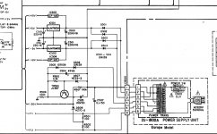
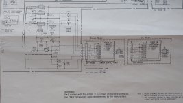
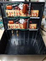
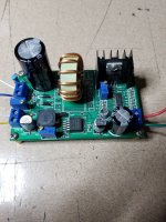
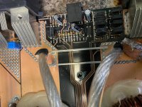
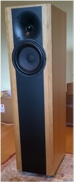
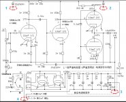
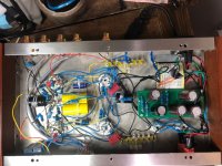
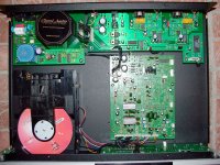
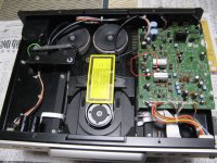
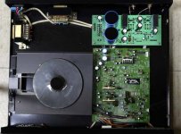
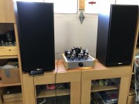
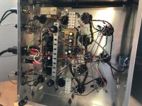
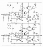
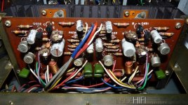
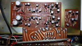
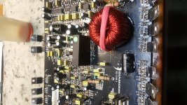
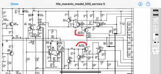
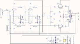
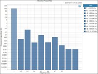
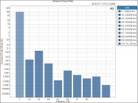
Hello, looking for some help restoring a surprisingly well built, decent sounding Nikko TRM-600 integrated amp circa 1976. Visual inspection showed all parts fine, filter caps look too good for 45 years w/ not a hint of hum. I left it on a 40W DBL for half a day to start but no sound on full power, tried a phone jacked into the pre-out/amp-in and it played music ok, so I Deoxited and worked all the bells and whistles and RCAs (and there are a lot) and got it playing. Did the bias and offset (Deoxited trimmers held up!) and got it in spec and it’s rock solid, playing well with its original mates, beat up Dynaco A25s that I also patched up. Amp sounds better than it should but it’s really too warm, bass heavy, and wooly, it’s been a long time since high school and I recall bassy and and warm was the goal back in ’76, but I think a complete recap should tighten and brighten it up for the better. I’m a sophomore e-tinkerer, been reading the forums/blogs but have a few questions. Below are the amp and preamp schematics, sorry it’s the best image resolution I could get from the PDF manual. Picts are from web, thanks go out to orig poster.

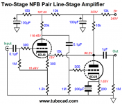
- I’m looking for advice regarding value or harm of using bipolar ES Muse caps for the 10uF caps doing coupling duty throughout the amp. If people here nix the idea it’ll be usual polar FC/FM/FR or KZ/FW instead. The .47 and 1uF couplers will get film caps. Is bipolar ES Muse a waste of effort?

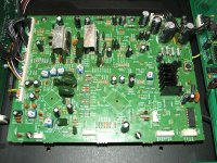
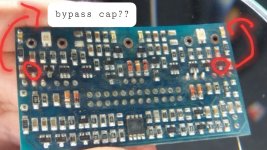
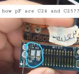
- Can someone point out the feedback circuit in the amp? I think it’s R667/C657. The only pf caps here are both discs, C657 and C661, leave well enough alone or try and sub polystyrenes? Tight, risky soldering here. Always worried of a trace lifting, it would be a hard fix.

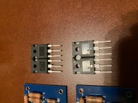
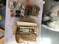
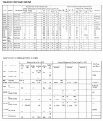
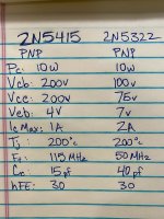
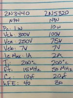
- I’ve included the list of transistors and diodes in the amp, if anyone spots ones known to be unreliable/noisy let me know as I’ll add their substitutes to my parts order and swap them out while I’m in there or at least set them aside for the future. The one that concerns me is the 2SA539 at inputs, but the amp is otherwise quite. And yes, I know, don’t shotgun it, do one thing, one stage, one channel, at a time.

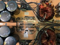
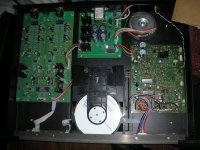
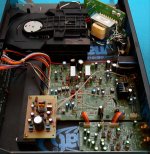
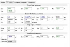
- I plan to up the filter caps from 6.8KuF to 10KuF unless people think the old S2HB10 8A/100v bridge will fail, it’s a TO-3 case so that would not be good. Go for it?

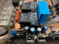
- This amp has speaker breakers not a relay protection circuit. I sprayed them out too and worked the buttons a bunch, no idea if they are working properly, obviously they close and pass audio but will they open on a short? Plus are these terrible sound-wise? Plenty of modern high quality hifi doesn’t use any speaker protection, is it stupid to bypass them? Anyone know if I can get new production drop in replacements? Mouser/Digikey link? I saw Velleman makes a relay protection board I could fit somewhere but I’d like to leave it looking as un-kluged as possible.

- It has a breaker for the mains too, I will leave it but maybe I should stick a real fuse in line with it? I'm in the EU/240V, amp's probably 30W, 2A slow-blow about right?

Any guidance will be much appreciated.

Attachments

  • Nikko TRM600 Main Amp Assembly.png
    Nikko TRM600 Main Amp Assembly.png
    243.1 KB · Views: 245
  • Nikko TRM600 Preamp Reg Assembly.png
    Nikko TRM600 Preamp Reg Assembly.png
    341.6 KB · Views: 197
  • Nikko TRM600 Silicon.png
    Nikko TRM600 Silicon.png
    700.5 KB · Views: 196
  • nikko amp web.jpg
    nikko amp web.jpg
    277.6 KB · Views: 154
  • nikko pre web.jpg
    nikko pre web.jpg
    284.5 KB · Views: 235
  • nikko trm 600 full schematic.pdf
    nikko trm 600 full schematic.pdf
    1 MB · Views: 311

Is a pre-amp required for Class A amplifier with digital source?

I am planning a Class A amplifier build. I'm leaning towards a version of JLH.

I notice that most pictures showing members' class A builds do not have volume pots. This makes me assume that most people are either using a pre-amp (active or passive) or are using a digital source where there is volume control (e.g. software based media player).


Given that the classic Class A designs come from a time before CD players and home PCs I'm wondering whether a 2V input still requires the use of a pre-amp to increase gain.


Some people insist that amps sound better with pre-amps. Some even claim that passive pre-amps improve the sound (how can adding a pot in a box and using a longer signal path improve things??). I don't really understand this even for an active pre-amp. I would imagine that this would only be the case if the pre-amp is very carefully designed to complement the power amp, which then removes any flexibility offered by having a device with volume and selector control that could be used for muliple power amps, meaning simpler and cheaper power amp builds. An active pre-amp then also need its own power supply and cord etc.

To me a pre-amp (active or passive) it is just adding another layer of potential degradation and/or a deviation from the character of the power amp. I feel like I must be missing something. By the way I have never owned a pre-amp, but like the idea of adding a (good) volume pot to active amps even if there is digital volume control at the source. Sometimes its just more convenient to twist a knob.

Old School Diamond Audio D3 1100.1 repair

Hello all, I have a couple Old School Diamond Audio D3 1100.1 amps (class D amp) which the output FETs failed on. After replacing the outputs, it's still dead. I checked for the gate pulse on the outputs and nothing so that leads me back to the class D modulator board which is where the problem lies. For some reason, they put the board in a little plastic box and filled it with potting material so there is no way to repair it. They were pretty paranoid when building this amp as ALL the ICs have their numbers grinded off, even the OP AMPs in the preamp stage. They didn't want you repairing this thing. I attached a picture of the board and the class D module is right in the middle with the green sticker on it. What are my repair options? I have 3 of these things all needing the same part.

Attachments

  • IMG_20160630_211624.jpg
    IMG_20160630_211624.jpg
    1 MB · Views: 148

SG3525 ferrite transformer calculation

I am designing a 300W car amplifier using TAS5630B. To power the chip I am stepping up the 12V input to 40V DC using push-pull topology. My controller chip is SG3525 and I am using a PC40 material T28X16X16 size torroidal transformer.

For SG3525, I choose Rt= 22K, Ct= 1nF and Rd= 56 Ohms. Which gives oscillator frequency of 64KHz. So each MOSFET is switching at 32KHz.

My question is during calculation of primary turn of torridal transformer which frequency, f I have to consider in the formula Npri= (VinX10^8)/(4XfXBmaxXAc) ? 32Khz or 64 Khz ?

Help!!! audison vrx 6.420

good evening, I open a new discussion because I was wrong to write under the old post of another user who had the same problem on a 6 channel vrx (ld1.2 cards) and had solved. In a few words, after 10 minutes of listening, the amplifier starts to emit background noise / noise. The problem lies in the modules ld 1.2 because if I insert those of the 2 channels vrx 2.250 it disappears. A forum user had identified the offending bjt and had solved by bypassing something. Would anyone be kind enough to tell me what to do and where to intervene? place photo of the ld 1.2 board (photo number 1 where I circled the bjt which seemed to indicate the other user as faulty and the capacitors on the side if hi understood well where he recommended a bypass but with what?) and a vrx 1-2 signal input module (photo number 2) where I would like to know if anyone can tell me the value of the circled capacitors not having an instrument that measures below nF. Thanks in advance to everyone who wants to help me. Greetings Mino

Attachments

  • 20200711_013844.jpg
    20200711_013844.jpg
    157.4 KB · Views: 219
  • 20200711_014337.jpg
    20200711_014337.jpg
    217.8 KB · Views: 107

Anyone recognize these speakers?

I picked up these Organic Audio Systems floorstanders knowing nothing about the brand, but influenced by the drivers installed, namely Hiquphon ow1 and Morel hu521.
The cabinets are decently made of what appears to be 3/4” mdf with a good thickness of maple veneer on both sides. The drivers occupy an estimated 0.31cuft volume at the top of the tower, ported with 1.5” x 5” long tube.
The crossovers are housed in the mid section, the components being glued directly to the enclosure without any component board. Film caps, (can’t see the brand), Mills resistors and three air core inductors of 16 or 18ga.
The lower third of the cabinet must contain some sort of ballast since they are very heavy, maybe 40 or 50lbs.
I wondered if these may be built from a kit, judging by the crossover section.
Any info will be most appreciated.
Stay safe,
Petr

Attachments

  • 39DBAB9D-D1C0-407C-9961-21C127D72A41.jpg
    39DBAB9D-D1C0-407C-9961-21C127D72A41.jpg
    327.6 KB · Views: 458
  • E06ADEE1-F1F6-4B45-AF3E-E9A5CEBE8DBC.jpg
    E06ADEE1-F1F6-4B45-AF3E-E9A5CEBE8DBC.jpg
    358.8 KB · Views: 459

Will these transistors work in this circuit of Marantz 500?

Hello all, I was given a Marantz 500 that was in pretty bad condition. Taking the top off you could immediately see components that had exploded, several burnt to a crisp. I decided to go ahead and completely tear it down and rebuild it. It was fully recapped, all tantalums were replaced, all carbon comp resistors were replaced, pretty much all diodes in the power supply replaced, new relays, and even though the outputs were measuring okay they were replaced with new On-Semi transistors that are more robust.

Anyways, I’m the driver board there are two transistors, Q117 and Q118, that have diodes (Fairchild FH1100) strapped across them and are thermally connected with compound. One board have the devices that are labeled in the manual, 2N5415 and 2N3440 with the FH1100 across them. I noticed on the other board in place of the FH1100 there were 1N4001s. I was told by a forum member well acquainted with this Marantz that the FH1100 is a hot carrier and the 1N4001 will not work in that position. The transistors under those 1N4001 were different as well, got to looking and nearly all of the transistors on the board are different than the other board, but the solder joints look stock.

Anyways, on the other board for Q117 and Q118 they are using 2N5322 and 2N5320. It took me awhile, but I for the correct FH1100 hot carrier diodes. Not I just need to know if these transistors will work in this circuit as the specs between the transistors are different. If the 25322/2N5320 will work I can finally move on. I’m hoping to get some input as I don’t want to put the amp all together only to tear it all apart when it won’t work.

Thank you for any help!

Dan

Attachments

  • C18385EA-3533-47E3-AEA5-45147B81BC41.jpeg
    C18385EA-3533-47E3-AEA5-45147B81BC41.jpeg
    890.9 KB · Views: 171
  • E88CA6E2-F2FA-4A77-869D-1A0AFC8009C6.jpeg
    E88CA6E2-F2FA-4A77-869D-1A0AFC8009C6.jpeg
    895.9 KB · Views: 163
  • 163C8A3D-DFE6-4DBB-8E11-BC8211DF665C.jpeg
    163C8A3D-DFE6-4DBB-8E11-BC8211DF665C.jpeg
    850.1 KB · Views: 167
  • 5467BAE0-E9DB-4987-B4A0-CED5AD05E3F3.png
    5467BAE0-E9DB-4987-B4A0-CED5AD05E3F3.png
    974 KB · Views: 166

Surprise, surprise!

Hi,
while tidying up my stashes today I surprisingly came across the devices shown in the pic. These are 16 pc. of 2SK135 and 18 pc. of 2SJ50 and were given to me by an Austrian friend in return for doing some favour to him about three decades ago. I've been searching for them since many years and yet was desperate to have lost them during one of many moves in the recent past.
Due to the screw marks around the holes, they're not new, but have been pulled instead.
Of course never in my remaining life I'll need sixteen pairs of those ancient Hitachi LATFETs, so I'm intending to sell most of them. Prior to this I'd like to examine them in order to avoid selling defective parts. But how to? What are the most important parameters, and how do I measure them?
Best egards!

Attachments

  • 20200715_163920_kl.jpg
    20200715_163920_kl.jpg
    99.9 KB · Views: 353

ultralinear pushpull amp design

Good evening everyone, about 10 years ago I started with the design of a stereo amplifier, thought of as a double monoblock in a single chassis.
The design was completely symmetrical, with constant current sources in each of the signal stages (two differential pair stages), with global VFB only. For this I considered a good open-loop performance with the idea of ​​having only 12dB of feedback. the tubes chosen were 12AX7A for the input stage, with a constant current source of 3mA in cathodes, this differential pair is followed by another that, in addition to amplifying voltage, has a greater capacity to deliver current to the grids of the output tetrodes, so for the second stage I used 6CG7 with a 7mA constant current source, the output is ultralinear connection with 6L6GC with fixed bias.
Total open loop gain was 46dB, (33.5dB closed loop).

The entire amplifier was designed by me, including the mains and output transformers. In both I used UI cores and two coils.
Some time ago I published the development in a forum in Spanish, since it is my mother tongue, both the calculation and testing process, and its DIY construction, although the measurements were very good at the time, they were made in a rudimentary way. Recently i was able to make more serious measurements with the help of a colleague, which I upload now, shortly I will translate the development and publish it in this thread. My intention is to start manufacturing it on a small scale with a view to marketing it in my country, although it's still a future project
I appreciate your comments and appreciations.

View attachment Roll Test ProudSound A50 V1.0.pdf

PD: sorry for my very poor english, i'm using google translate for now.

Attachments

  • schematic.jpg
    schematic.jpg
    108.5 KB · Views: 351
  • Distortion Product Ratio 1dB below cliping.JPG
    Distortion Product Ratio 1dB below cliping.JPG
    70.1 KB · Views: 349
  • Distortion Product Ratio 1W.jpg
    Distortion Product Ratio 1W.jpg
    69.9 KB · Views: 329

please critique this sealed 3 way sealed studio monitor idea

I have been on a quest to build a medium/large format sealed studio monitor with a comfortable peak SPL potential of ~117 dB @ 1m. I have started a couple of other threads in this regard... regular members may kindly excuse me for the badgering, I assure you that the idea is evolving (with your kind inputs).


TsEF39lV1Zf2sXQzsMxDy5vyTM45I_qWuQ8wPtXhJaecZF0JVN8CWzHzJqZfrofG1lXPuHqxm1fD4Ts-ztcA13yWUMWNopWsMR84eMC5EDCvuT3f2pxuLi7mCtr9Clg4tNybsB6C2A=w2400


The drivers I'm looking at are:

LF - SB Acoustics SB34NRX75-6
MF - Scan-Speak 18M/4631T
HF - Wavecor TW030WA11

DSP and amplification will be courtesy of a Hypex FA-253.

Enclosure volumes TBD depending on site of installation, and crossover points/slopes TBD upon testing - only constant is that the focal point (between the midrange unit and tweeter) will be @ 4' from floor level - the studio standard.

Please take a look at the above idea, and help me understand what challenges I will be dealing with here.

Ibiza Sound Combo210 buring TDA8950 chips

Ibiza Sound Combo210 burning TDA8950 chips

Hi there.

This is my first post in this forum, hope that someone more experienced than me can help with my situation.


I have one Ibiza Sound Combo210 on hands that works with a TDA8950 based amplifier.


When I opened it I could see that it was repaired before. There were two bodged regular resistors in place of two SMDs. One was visibly burned. I measured them and they are 10Ohms (agrees with the TDA8950 datasheet) that connect to VDDA and VSSA. The one that was visibly burned was the VSSA one. I replaced the one that was not burned with an SMD one like it was originally and put the removed unburned it in place of the burned one.


I replaced the TDA chip and the system worked for a few hours and then burned again. The resistor is again burn looking and the resistance dropped about 3Ohms (it didn't go directly short or open).


I measured the input voltage and it is about - 37.5 and + 37.5 Volts.


I don't know how hot this amplifier is supposed to run, but I measured up to about 80ºC at some spots of the board being the two resistors close to the big capacitors de hotspot at about more than 10ºC compared with temperature of the TDA chip zone. The power supply also runs very hot at over 100ºC.


I'm attaching pictures of the board for you to check.


Any help would be sincerely appreciated.

Cheers.

Attachments

  • 20200715_175137-2560.jpg
    20200715_175137-2560.jpg
    425.8 KB · Views: 85
  • 20200715_175151-2560.jpg
    20200715_175151-2560.jpg
    385 KB · Views: 88
Projects by fanatics, for fanatics
Get answers and advice for everyone wanting to learn the art of audio.
Join the Community
507,772
Members
7,887,910
Messages

Filter

Forum Statistics

Threads
406,206
Messages
7,887,910
Members
507,772
Latest member
Hypertone