Hello again, I have this kicker zx1500.1 the problem I have is that I get a sound in the output similar to a tone of 900hz piiiiiiiii and it mixes with the audio that I introduce, the audio sounds good but that sound is mixed if I remove it the knob card still persists only when I remove the drive card nothing sounds anymore I have good voltages +90 -90 -12 +12 +5 does anyone have any idea what it will be?
Attachments
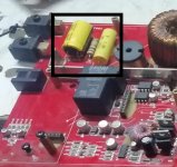
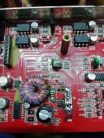
The attachment shows R139 & C112. R139 ohm 2ohm/3watt may be out of value, also check C112-10uF/200V.
L100,L101,C108,109,111 and R134, along with R139 and C112 the output filter and zobel.
If after checking and replacing R139, the 900hz tone doesn't disappear check the other components.
L100,L101,C108,109,111 and R134, along with R139 and C112 the output filter and zobel.
If after checking and replacing R139, the 900hz tone doesn't disappear check the other components.
Attachments
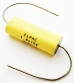
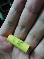
If you asking if that is the correct value, then yes it is. If you are concerned that C111 is stuffed with a non factory cap, then post a clear pic of C111 as it is on the board and I will verify.
c111 is 200v 1.8uf ?, like this
in the end all the capacitors and the c111 were good, only that it no longer gave audio I have in the drive the voltages well + 5v -12 +12 and in the pre-expansion also +110 and -110 but it does not sound it does not produce any sound, how can i know if the terjta drive is working
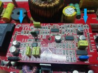
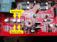
One attachment labeled ZX15001_drive_pins shows the arrows pointing to the Test Points on the PWM board where you can place the red or scope probe of your meter or oscilloscope.
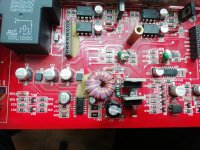
The other attachments labeled SGND_Scope_GND will show a long bar, which is SGND or signal ground. Place black probe or scope ground anywhere along this bar.
The other attachments labeled SGND_Scope_GND will show a long bar, which is SGND or signal ground. Place black probe or scope ground anywhere along this bar.
Attachments
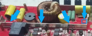
This is the small power supply for the drive circuit. U1-TL594 is the PWM that switches Q12 and Q13 across T1. D8 and D9 rectify the secondary swing and charge up C11 and C12 to about +17 Vdc.
The attachment shows where to place the voltmeter probes to measure the 17 volts. C11 and C12 are not connected and floating from the main power supply. Therefore you will have to measure each separately.
If you don't see 17 Vdc, Q12 or Q13 my be shorted. I noticed there has been some repair work to a burnt trace and a 10 ohm resistor added. Be sure that this is connected to the drain of Q12 and C10-1nF.
Attachments
I will need to check.you know that mosfet or transistor goes here it brought b31n20d take them out and they are wrong
ok, it had 2v on legs 8 and 9 tl494 and a distorted square wave, so I changed the tl494 and I already had tube 3v for 9 and 10 and clean square wave so I changed the Transistors I put irfz48n turned on the amplifier and already tube audio as a principle, i'm tracking the tracks to see what it feeds do you know what it feeds?

- Status
- This old topic is closed. If you want to reopen this topic, contact a moderator using the "Report Post" button.
- Home
- General Interest
- Car Audio
- Kicker zx1500.1