Scanspeak 10F/8424g 4"Mids Alternatives??

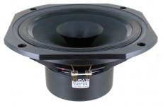
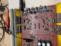
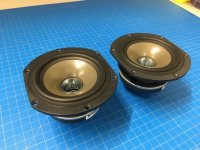
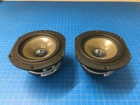
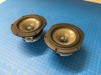
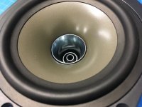
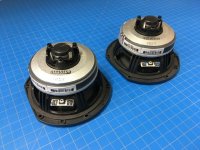
Hi 🙂 , Im restoring a pair of THIEL CS2 speakers and sadly the VIFA stock ones are Blown. In my research trying to find the replacement for the stock model I got the Scanspeak 10F 8424g as the ideal replacement BUT they are too expensive. My other options are the 8 OHM FaitalPro 4FE32 and 4FE35 for less than half of the SS price.

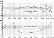
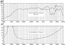
Datasheet 4FE32: https://faitalpro.com/en/products/LF_Loudspeakers/product_details/datasheet.php?id=401005100

4FE35: https://faitalpro.com/en/products/LF_Loudspeakers/product_details/datasheet.php?id=401005150

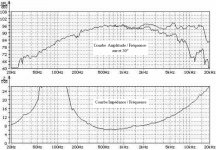
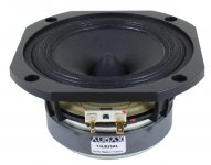
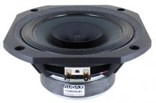
Scanspeak 10F 8424g:
https://www.scan-speak.dk/datasheet/pdf/10f-8424g00.pdf

Would they work for as replacement for my Thiel's ??? Is there a better option??

Attachments

  • 116723904_304964977522282_5640310365258742585_n.jpg
    116723904_304964977522282_5640310365258742585_n.jpg
    106.5 KB · Views: 278

Wanted Seas 25TFFN/X or similar tweeter for T17 coax H0723

Hi all,

I am hoping to repair a Seas G17 coax... marked as H0693, which has some tweeter damage (shorted coil). It seems to be a version of the H0723 T17REX COAX/F but with the cone in fibreglass.

The specs describe the tweeter as a 25mm, 6ohm part based on the H0615 25TFFN/G but with different housing for coax mounting. There are some references on the internet to a 25TFFN/X which looks like it may be the right part.

I'm looking for any suitable parts or donor speakers that I may be able to use for the repair. Information or advice also gratefully received!

I think that the suitable parts may be:
25TFFN/X. Seas 25TFFN/X (6Ohm)

or whole donor coax:H0489 P17REX/XF
Perhaps this also uses the same tweeter?
H0487 MP14RE/XF


Thanks!
Daniel

Rega Radio

The Rega Radio and Radio R and Radio 2000 (with remote control) were essentially re-packaged NAD 402.

Attachments

Rega Mira 2000 - Schematic Diagrams

For reference:

Attachments

  • Like
Reactions: rookakoma

Rega Elicit - Clamshell -Schematic Diagrams

For reference.

Attachments

  • RegaElicitDCProtection.jpg
    RegaElicitDCProtection.jpg
    189.9 KB · Views: 325
  • RegaElicitFrontPanelPCBImplementation.jpg
    RegaElicitFrontPanelPCBImplementation.jpg
    182.8 KB · Views: 296
  • RegaElicitFrontPanelSchematic.jpg
    RegaElicitFrontPanelSchematic.jpg
    438 KB · Views: 276
  • RegaElicitInputTapeAndRelayPCBSchematic.jpg
    RegaElicitInputTapeAndRelayPCBSchematic.jpg
    430.5 KB · Views: 353
  • RegaElicitLeftChannelDiscInputSchematic.jpg
    RegaElicitLeftChannelDiscInputSchematic.jpg
    441.7 KB · Views: 453
  • RegaElicitLeftChannelPowerAmpSchematic.jpg
    RegaElicitLeftChannelPowerAmpSchematic.jpg
    283.9 KB · Views: 368
  • RegaElicitLeftChannelPowerSupplySchematic.jpg
    RegaElicitLeftChannelPowerSupplySchematic.jpg
    349.6 KB · Views: 334
  • RegaElicitRightChannelDiscInputSchematic.jpg
    RegaElicitRightChannelDiscInputSchematic.jpg
    436.4 KB · Views: 290
  • RegaElicitPrincipalPCBImplementation.jpg
    RegaElicitPrincipalPCBImplementation.jpg
    889.5 KB · Views: 307
  • RegaElicitRightChannelPowerAmpSchematic.jpg
    RegaElicitRightChannelPowerAmpSchematic.jpg
    268.2 KB · Views: 311

Rega Brio - Clamshell - Schematic Diagrams

For reference.

Rega Brio (one channel dead) - Page 2 - diyAudio

This amplifier design has an interesting history. It was originally designed by Texas Instruments (i think in Bedford England) as the "Texan" kit for "Practical Wireless" magazine back in the 1970's.
Rega borrowed the design but used more rugged output transistors than the original TIP41/42.

The main feature is that the output stage has some voltage gain which allows the op-amp to run off low voltage supplies.
I believe the original Texan design did not have quiescent current setting adjustment which can give the dreaded crossover distortion.

Attachments

Dayton 21 - Vortex and Kraken

Disregarding the cheap and corny sounding names for now, I got an email about these today.

Dayton Audio PSS545HE-4 Vortex 21" Pro Subwoofer with 5" Voice Coil 4 Ohm

Dayton Audio HTS545HE-4 Kraken 21" High Excursion Subwoofer with 5" Voice Coil 4 Ohm

At first glance these appear to have some value. Specs are very similar, maybe same motor and frame and just different soft parts? Klippel verified 21 mm xmax which is quite a bit considering most high xmax drivers are definitely not Klippel verified. "Unique over-excursion protection system warns you just before catastrophic failure" means this is a hard bottom driver. It's got a shorting sleeve but ridiculously high inductance.

Interesting but I have to check the data sheet and see what it sims like.

Recommendations for Wire harness/ Umbilical cords between chassis

Wondering if there is a secure ready made harness available to connect 2 Chassis's (Chassi?) for a power amplifier. One enclosure will house the Electronics and heatshink, the other, the PSU.

I need at least a 3 gang / cable connection (prefer 6) that can be plugged in (screw type preferable)

Is able to handle 20amps sustained, and higher peaks. I have looked at Mouser... but I get lost in the tens of thousands of skus they have...

Any pointers would be appreciated.

Bluetooth Speaker

I am new to this so please bear with me. Also I hope I can get some responses.

I had an AmazonBasics Bluetooth speaker with crushed woofers so I decided to use the card inside to make a better Bluetooth speaker out of 1 old Sony SS-EC50. It sounded quite good, but I quickly learned that it didn't get very loud.

One of my old teachers says I should wire the output from the Bluetooth card to a 3.5mm jack and plug that into an amp which then goes into the speaker. That makes sense to me, however, I'm struggling to find battery powered amps because I still want it portable.

Hopefully someone can help. Thank you in advance!

A big budget sound rescue - The dreaded Jensen JHS 3315

Don't feel sorry for my dumb ***. I did the unthinkable. I purchased a set of speakers based on the fact that, I myself cannot afford a set of Klipsch Heresy used or new. So with a total budget of 100 dollars. I looked for a set of speakers I bought when I was 15, 26 years ago.
The Jensen CS 315. Well, those sell like hotcakes apparently. That whopping 20 bucks means they are gone before you find them. So I found a set of JHS 3315. The predecessor.

The owner kept complaining. "They are vintage". "Your getting a steal of a deal". "Are you sure?" I asked him. "I'm giving you 30 and everyone else is paying 20!". So after getting them home, I set them up knowing damn well that they had the same issues of the CS 315's had 25 years ago. No crossover, just 2 caps on a printed circuit board glued to a input cup. The 15" woofer was playing full range and drowning the midrange out. The midrange would poke its head up when A LOT of power was applied. As well as the tweeter would get uncontrollable. Let's go see what Amazon can do to fix this poopy problem.

Remember, my budget is 100 dollars. Total. I would use Parts-Express. But an Eminence crossover will put me to the limit. This may need mids and tweeters. So let the bargain shopping begin.

What I came up with was an Uxcell 3 way crossover. Crosses at 850/4000. Good enough. Stuffed polyfil into the boxes and installed crossovers. Still testing, but automatically the difference is night and day. I removed the metal grill screens off the tweeter and mid. This also made a huge difference. I might say now. They are respectable. But can still be better.

Looking now for a 5" midrange option. Should I stay closed back? Open back with an Eminence cup? Or spend a little more than I wanted and go dome?

Western Electric 1928 - How far have we come in the last 100 years?

So I saw this video yesterday and it got me thinking. How far have we really come in the last 100 years in speaker design.

1928 Western Electric cinema speaker - YouTube

Although it is to big a project for me to do currently, I am curious to know how much better we could make this speaker with current modeling, design, materials and drivers.

Wouldn't be interesting to see how a version of this speaker, using all we have learned would compare to the original?1

How are (Lowther) phase plugs aligned?

I got curious when I came across this statement somewhere on the internet as I assumed phase plugs are centred with the cone. Perhaps there is an advantage in having a small offset, for the same reasons one offsets a driver in a baffle. Anybody got any additional insight to share ?

“I recall, however, that Scott Fraser said that the phase plug mounts eccentrically in this driver, which made aligning the cone especially difficult. “

from: High Efficiency Speaker Asylum

Carl Huff is cleaning out his parts closet - Lots of goodies!

Hello all,

I am downsizing my parts stash and are making lots of precious items for sale. The first that I am looking to sell is my stash of Slewmaster v1.1 3P EF3 OPS PCBs. This was my favorite output board it works well! There are 10 PCBs in this package. The boards were professionally fabbed by PCBWay. How about $45 for the entire package? And please don't ask me to sell less than the described 10. Share with your friends! BUILD MORE AMPS!!

Attachments

  • PCBs_00.jpg
    PCBs_00.jpg
    691.5 KB · Views: 1,001

Noise in tube preamp (not hum)

I just built a nice kit based on Kondo kSL M77 - schematic and photo of the layout here: https://www.lencoheaven.net/forum/index.php?topic=29419.0

I modified power supply for heaters using DC voltage regulator per this guide: This guide is to help you build the DOUK KSL-M77 Preamp clone kit.

After some tweaking of GND and Earth wires - using ground breaker, twisted input and output wires, optimal position and orientation of power transformer,... I managed to reduce hum to be almost not audible.

However one issue I have is the noise - I man white noise (not um, not buzz). Some observations:

- it is audible even 2 meters away from the speakers
- preamp is using brand new 12AY7 tubes (TAD)
- noise is caused by the preamp (I tried to use other solid state opamp based preamp and there is no noise then)
- it is audible with both phono and line inputs
- it is independent on the volume control - noise is constant
- I checked with microphone close to speaker and the noise has almost flat frequency spectrum - white noise
- it is audible also with line input selected (seems no problem with phono section)
- there are two sections in the line amp part of the circuit - schematics here: https://www.lencoheaven.net/forum/index.php?topic=29419.0 and when I remove the first tube in the line preamp section there is no effect - still the same level of the noise
- however when I remove the last section of the line preamp - “last” tube before preamp output (cathode follower - buffer?) the noise disappears.
- I tried also to change tubes - no effect
- I also tried to change the heather DC voltage from 12.6V to 11.5V and the white noise reduces a bit but it is still audible in the listening position
- the noise is in both channels

I fully accept that tube will have more noise compared with solid state - especially in MM phono preamp. However as it is audible 2 meters aways from the speaker and also with the line level input I think it is not ok.

Any idea what can be wrong? (Based on above observations it seems to be something with the last section of the circuit)

Integrated Amp Control Board

Hello all! Long time lurker, first time poster. I am not sure if this is the best place to post this. Please let me know if there is a more appropriate forum.

Here goes:

I am designing a board that will allow me to control my SCA-35 with my phone. The controller features 4 analog inputs and 4 optical inputs. The optical inputs feed into a DAC board that will be housed in the amp case. At the heart of the design is the ESP32 IC. I am using a rotary encoder for manual power and input selection and an Alps motorized pot for volume control. Before I have the board made, I was wondering if any of you would be willing to review my design to point out anything I missed or improvements I can make.

Any feedback you care to offer will be much appreciated!

Schematic_AmpControl%20V4_2020-07-30_14-21-03.png

My first DIY Subwoofer using Dayton Audio SD270A-88 10''

Hello All,

I am new to this forum, I have seen so much knowledge has been shared in this forum in DIY stuff. I am planning to build a subwoofer with DA SD270A-88 10''. I have simulated the box with bass box pro. I have run the driver parameters and calculated enclosure properties. I have attached the file too please go through it and tell me if I am missing something. Thanks in advance for your valuable inputs.

I chose vented enclosure, I have seen some old thread related to the same driver but information are not complete, feel free to suggest me with different type of enclosure.

As I am new to DIY, please bear with my overnight knowledge.

Regards
Jeanpher

Attachments

Could a beginner instal VVR on a AC4TV?

Hello, this is my first time posting here!

I’m thinking of installing a VVR from Ampmaker into my Vox AC4TV as I’d like to get some dirtier sounds at lower volumes. I’m not very experienced with electronics but I recently resoldered the connections on my telecaster selector switch, opening the thing up along the way, so I reckon I could put the VVR kit together without any problems. But I’m not sure if a novice like me would be able to install it in the amp itself.

I’m fairly technically minded and can follow instructions but I can’t read a circuit diagram, as yet. So I’d like to ask for advice from anyone out there who might have carried out this mod.

- How many steps are involved in the installation? I can only see three cables coming off the VVR kit - does it simply require three wires to be soldered in somewhere?
- Does anyone by any chance have something that approximates a step-by-step guide to installing this VVR with photos of the circuit board rather than a diagram?
- Is it possible to install the VVR and retain the AC4TV’s existing ‘attenuator’?

Attachments

  • vcb01.jpg
    vcb01.jpg
    31.7 KB · Views: 154

Diamond buffer not performing well How to design and Optimise for headphone amp.

I am looking ake a headphone amplifier. Since op amps has limited current capacity I was wondering about output buffer. I wanted to use diamond buffer. I simulated a few output buffers and diamond buffer performed the worst.😡

I have been searching internet but could not find any article on how design diamond buffer, how to select bias current and driver emitter degeneration resistor. 😕

According Ltspice simulation a simple Push Pull is working better than Diamond buffer and paralleling op amp as unity gain buffer out performs all of them.

Simple push pull performs better with increasing the bias current but Diamond buffer suffers.

For similar bias current Diamond buffer worse than Simple Push Pull Circuit.

Tweaking current and driver emitter degeneration register does improve thd a little bit. But I am clueless as how to properly select bias and degeneration register for any given component.

Any assistance would be greatly appreciated.

simulation file included.

Attachments

555 timer and TV refresh rate

Hello,


I'm trying to generate a composite video signal. I had done this many years ago and it was working with an old TV with a 50Hz refresh rate. That is a 25Hz frame frequency and 625 horizontal lines. The circuit was very simple and it was based on 555 timer. Please see attachments. But now I want to make it work with a PC monitor and these have a 60Hz refresh rate. So, the question is how to adjust the circuit for 60Hz? I guess for the vertical sweep it might be as easy as to adjust the frequency with the trim pot.(?) But I can't find any info about the horizontal sweep i.e. the square wave shape. If you could enlighten me about all this or if you could suggest another circuit that works it would be great!

Attachments

  • Schematic.JPG
    Schematic.JPG
    61.7 KB · Views: 142
  • a.JPG
    a.JPG
    16.1 KB · Views: 134

Help! Identifying resistor type

Hello everyone, thanks for reading my question.
I am working on an old Crest Audio 8001 amp. One channel is down and after taking some readings on all the resistors I am replacing all the faulty ones one by one(alongside other parts of course). There are a few on the PCB that I can not identify in terms what material (carbon, metal etc) they are made of as well as what power they would be. They are approximately 9mm long and brownish in color.

I am wondering are there any real significance of this at all ? Can I replace these with any type with of course the same resistance, tolerance and power ?

Being a high powered class H amp this, i would like to make sure I choose the right components and wont be let down on a 20p resistor. Your advice will be much appreciated !

I am attaching a couple of photos with the PCB the resistors in question are the ones in the yellow rectangles.

Attachments

  • IMG_20200729_193908.jpg
    IMG_20200729_193908.jpg
    448.2 KB · Views: 187
  • IMG_20200729_193850.jpg
    IMG_20200729_193850.jpg
    526.3 KB · Views: 211

Found 41Hz kit.

So, I was cleaning out old boxes for a recent move, and found an unbuild 41Hz AMP9 kit still in it's plastic bag. Was thinking of building it up and using it to repower the old 1965 intercom system in my 'new' house.

No paperwork with it, though.

What are the odds anyone has got some old pdf's for this thing? I know 41Hz is long-gone - and I found schematics on here for the AMP9-BASIC - but that's not what I've got. As far as I can tell, it's just called AMP9 Low Profile / 14.5V.

Sampan, a small FTL speakers. Is there a DIY competitor?

Hello Gents,

The Sampan: ( The Sampan FTL ) has gotten a lot of very positive reviews. I'm wondering if there is a DIY equivalent design around. I recently have been listening to some TABAQs I built a couple of years ago and am greatly appreciating some of their virtues that I had forgotten about. I'm hoping that a Sampan clone will give me some of that quality of sound in a much smaller cabinet volume. Any information about a possible clone or similar proven design would be welcome.

Best,
Jay

Audax Full range drivers frequency response

Hi.
I added the photo of 5",6.5inch and 8" audax drivers with order.
Which one of them can I use a full range without any correction circuit and without any irritation?
I do not know which frequency peaks more important.
But I am guessing, it starts with 2-8khz??
What is the important thing, peak degree/sharpness or just the amount(db)?
I am guessing frequency response change wrt enclosure.??

When I tried to understand this graphic:
5" 5-6khz 6db peak
6.5" 7khz rising response
8" 2-4khz 8db peak and at 7khz rising response

But also I thing 5" has peaks at 2,7,10,15khz
How much are these important?

I prefer the full ranges with whizerless and changeable phase plug. (I learned from madisound, these phase plugs super glued)
But if it will have high frequency irritation, I can choose whizzer ones easily 🙂

Attachments

  • 13LB25AL-curves.jpg
    13LB25AL-curves.jpg
    180.7 KB · Views: 414
  • 17B25ALBC-curves.jpg
    17B25ALBC-curves.jpg
    177.8 KB · Views: 403
  • AM21LB25ALBC-curves.jpg
    AM21LB25ALBC-curves.jpg
    172.7 KB · Views: 393
  • 13lb25al.jpg
    13lb25al.jpg
    144.1 KB · Views: 442
  • 17lb25albc.jpg
    17lb25albc.jpg
    136.7 KB · Views: 393
  • am21lb25albc.jpg
    am21lb25albc.jpg
    118.2 KB · Views: 173

Secrets of binding posts

The problem is i have binding posts such as those in following links :

https://hfc-fs.s3-eu-west-1.amazonaws.com/s3fs-public/jantzen-012-0170-binding-post-800.jpg

https://hfc-fs.s3-eu-west-1.amazonaws.com/s3fs-public/jantzen-012-0170-disassembled-view-800_0.jpg

they come with two star-like circles that i'm not quite sure what to do with.
Anyone knows what should be the correct sequence of nuts and those circles when mounting ? XD

full range + woofer OR full range + tweeter ?

I have made single driver full range speakers and love them. But there are compromises and I'd like to explore adding another driver to the system. I plan to bi-amp so that the XO will be in the line stage (active or passive). And I would like to start my explorations with Open Baffle but would be interested in opinions to the contrary.

I see two options,

1) small full range (e.g. 4" size) + woofer (e.g. 15" size) with XO below the 'critical audio range' at around 300Hz

OR

2) large full range (e.g. 8" or larger size) + tweeter with XO above the 'critical audio range' at around 3kHz

What are the pro's and con's of these two options ?

Xilica XP 3060 died

I go to turn the Xilica on today and got a moderate pop out of the speakers and then nothing. Worked fine yesterday but today not a thing. The display briefly shows as normal and then goes to faint flashing or nothing or full display of every line in there in each space.


Hoping this is not fried but not optomistic. problem with Xilicas from day one is really crap documentation and information so hoping someone here has ideas.

  • Locked
Mole 4, Humans Zero - What to do?

Perhaps an odd topic for DIYAudio, but I really need to drive out this little critter!

- Tried flooding his hole / tunnels with water. Nope

- Tried spring traps from ebay - the mole just goes around them, eats off the bait w/o springing it.

- Tried poisoned peanut butter. Adams, the good stuff - I cant stop eating it. Just ignores them.

- Tried a couple of crap drivers (after reading success on the 'net: How to remove moles from your yard) wrapped in plastic, playing very distorted FM pop 24 hours. He just seals up his tunnels around the speaker - and makes new mounds within a meter of it.

Goodwill isnt taking donations, so I gave up getting rid of a Velodyne 12" sub I picked up there. (I'd use it, but it has a habit of coming on full blast with some kinda crackling noise at 3AM...) Maybe using a bigger gun?

He wont be able to just seal off the sound from that - hopefully. Trying the most obnoxious sound I could get from my FG, settling on a square wave sweep from 5 -> maybe 20 Hz - hopefully sounds like a stampede up there to the mole.

I've got the level set to a decent, hopefully non-destructive level. Heatsink gets hot, so I put a fan over it. The Velodyne immediately got covered in dirt and dust on first exploration of the idea, so I put down a piece of plastic and then a piece of rubber foam to get a bit better seal - to the ground. We'll see what happens.

Any ideas would be appreciated. Thanks.

Attachments

  • DSC02460.jpg
    DSC02460.jpg
    613.2 KB · Views: 255
  • DSC02461.jpg
    DSC02461.jpg
    694.2 KB · Views: 256

Selecting speakers for salvaged "boxes"?

I'm looking for advice on considerations I should make when repurposing some items as speaker boxes.

Right now I am most concerned about selecting proper Vas and Qts. Is there a way to size this from the box size? I've only seen the reverse: box sized from these values.

For instance, last night I was trying my hand at this. The container interior dimenstions are 8.75"Wx11.7"Hx6.5?"D for a total of 0.385 cu ft (10.904 cu L). The front has room for ~5" cut out and a 1.5" tweeter cutout. The back I was going to replace (pegboard like holes) and either vent and/or put a (sub)woofer in.

Rightly or wrongly, I converted the Parts-Express woofer selection guide into a pivot table so I could sort and filter on Vented Volume, F3, Cutout, W_RMS and SPL.

I started with woofer
Tang Band 6.5" 4ohm w/ 50W RMS, 83 db SPL, 38Hz F3_vent @ 0.33 cu ft.

Tang Band 6.5" | 4ohm| 50W RMS| 83db SPL| 38Hz F3_vent @ 0.33 cu ft.

Filtering on box vol and cutout, I added this mid-woofer:
Tang Band 5.25"| 8ohm| 28W RMS| 88db SPL| 73Hz F3_vent @ 0.27 cu ft

Am I on the right track?

Lower Voltage Triodes?

I've been experimenting with an all-tube headphone amplifier for a bit and have more or less settled on the 6gc5 pentode for power out. It prefers B+under 200vdc and I'm particularly fond of the punchy sound. Triodes using the same B+ supply wind up with 70-120v on their anodes because of my plate resistor choices. (depends on tube, bias and resistor value) I'm really satisfied with the sound as-is, but it's leaving me wondering if it would be even better if I could be giving the tubes more of what they want, you know? Are there any good twin-triodes out there that perform their best (or thereabout) within that voltage range? I've tried 6FQ7, 6EU7, 12AT7 and 5963 so far. Some give specs for my voltage range but the tube specifications state that such voltages are far from optimal. Admittedly I may be reading them wrong though. I'm also picking up a boat load of RF from the audio source cable. I can easily hear everything that my bench PC (audio source) is doing. Hi-mu triodes seem to exacerbate that but I'm going to have to take measures to stop it in addition to using a shielded enclosure and cables. Maybe bias the front-end cold to lower gain and/or use medium mu triodes? I'm not sure. As-is, it has a pretty stupid amount of headroom so lowering output isn't an issue whatsoever.

WTB: Fostex FT96H tweeters and Mediator 40 SUT

Want to Buy:


Fostex FT96H horn tweeters (pair)

Mediator 40 SUT (MC step up transformer made by Audio Creative)

Please drop me a note if you have one available, even if you're not in the US!
I'm located in St. Louis, Missouri, USA
Thanks!


Tom

Attachments

  • 2809652-526f4e0c-fostex-ft-96h-alnico-tweeters.jpg
    2809652-526f4e0c-fostex-ft-96h-alnico-tweeters.jpg
    61.2 KB · Views: 103
  • 2809399-61430046-audio-creative-mediator-40-step-up-transformer-sut.jpg
    2809399-61430046-audio-creative-mediator-40-step-up-transformer-sut.jpg
    79.3 KB · Views: 102

Napa Acoustic 208A or Mistral DT 307B

I have a Napa Acoustic 208A AKA Mistral DT 307B hybrid integrated, with a pair of 6N1 in the pre. Napa Acoustic is no longer in business. Only the right channel works. Only the right tube lights up. And I have swapped left and right tubes, no change.
I have opened up the unit and checked the electrical connections. Is there an internal component that will fix it most of the time? Troubleshooting this is not in my skill set. Switching out a component is.
Thanks,
Joseph

Channel switching

Hi everyone, I'm trying to design the footswitch for my new three channels amp, but I'm not sure how to pull this off. The amp has three channels: I have two relays that takes care of the channel switching. When they are activated, they will switch to clean or lead. When these two relays are not connected (i.e. the GND is lifted), the amp is in the crunch channel. Channel switching is currently controlled by a three position panel switch and this works just fine.
In addition, I also added a post FX loop additional master volume which is controlled by its own dedicated relay to GND. I would like to have all this switching in an external pedal: normally I make two channels amp, so I can get away with a simple stereo jack. This time, however, I want to be able to switch between the three channels (clean/crunch/lead) and turn the loop on/off as well. I figured I could use a 5 pin DIN port to transport all the signals I need, but have no idea what's the easiest way to wire this up without using microcontrollers or PICs... Do you guys have any suggestions? I'm a bit lost 🙁

Bought Sure 3x200W AA-AB35281 board, but it's hissy / not silent.

For my active speaker build I bought 2 of these:

Sure Electronics AA-AB35281 3x200W Class D Audio Amplifier Board - T-Amp

but even when nothing's connected, it's noisy.

EDIT:
Using a Connex 600W SMPS: SMPS600RS | Connex Electronic

I need advice on either how to make it silent (Don't think that's an option - but hey, if anyone's got a magic tip I'm game 🙂),
or advice on decent class D boards to provide individual amplification to my drivers.

I'm building a set of 3 way speakers, using a tweeter, full range driver, and subwoofer driver (TB 1139SIF).

I'm not looking for club volume levels, just casual listening - so the tweeter and mid don't need much watts. The 1139SIF might need some oomph since it's 83dB....

I noticed 3E Audio used to have a 3-way amp:
TPA3251-3CH-200W | 3e Audio

but I contacted him and it's out of production...

Any recommendations on decent class D amps I could use for this setup?
(A 3-way amp like 3E's would be awesome but my Google-fu has turned up zilch..)

500W of ICEpower for USD$100, deal or not?

In several retailers there are selling the closeout VOCOPRO FeatherAMP 500W for under USD$100.-

That amp uses the ICEpower 125ASX2, which can be used in stereo (125wpc@4ohm) or BTL (450w@4ohm).

The amp also comes with gain knobs, a design that can be used as a plate amp, a 1/8 TRS pre amplified input and also balanced input.

The VOCOPRO company is California based, so I would assume they used genuine ICEpower products.

I am kind of wanting to buy it to power my Auralex bass shakers or maybe another subwoofer.

So... is it a good deal or not? What do you think?

Looking forward to your replies and comments.

Very rare Motorola/bgh turntable HELP!

P1020754 — ImgBB
P1020741 — ImgBB
Hi there, I got this Motorola SC-320 AM radio turntable combo from Argentina.
Radio works for a while, then it shuts. Turntable moves and stucks.
I want to try to fix it but I don't even know what I see.
Any help?
Has anyone seen a similar Motorola combo? I need some basic instructions on how this things work so I can check it out a piece at the time.
Where's the amp line in? How could I feed it another sound singnal to test the amplifiying system?

Thanks in advance.

Slot ports or round ports .... which is better ...?

Hey guys, now i am ongoing building a subwoofer project ...

I need help ... the ports for subwoofer i found locally were too small ..... to make things easy for me to work ..... i know i can use PVC pipes as ports .... but there are no way to make flares for the port ends ....

so therefore considering the use of slot ports came to my mind .... can give advice .... slot port or rounded port is better for subwoofers ....?🙄

Do I Need Measurement tools?

So i have future goals of building large interesting horns but for the moment I know nothing, have built nothing and don't want to spend money on drivers to learn how to build cabinets if i don't have to when i have a whole bunch of different sized crappy speakers i can pull apart.

Obviously i have no idea of the t/s parameters for any of these drivers i have so i made a cable and used REW to find them. credit and thanks to this video How to measure Thiele Small parameters using your SOUND CARD - YouTube for showing me how to do that.

Now I have designed a reflex cabinet and realized that i want to be able to test it after its built so i started looking at the omnimic v2 that is bundled with the dayton dats v3.

as someone who wants to spend as little as I can during the learning process I'm just wondering if its worth forking out for both the mic AND the DATS v3? Does the DATS v3 do anything REW (with homemade cable) doesnt do? or will i be ok just buying a measurement mic and using REW to find the t/s parameters of my unknown drivers?

Sorry for long winded storey, just wanted to make sure people know my goals 🙂 cheers!

Driver spacing and crossover frequency

Been reading Vance Dickason "Loudspeaker design cookbok"
Regarding driver spacing it is recommended to keep drivers as close as possible, and to make sure this distance is less than one wavelenght at the crossover frequency.

So typically for a 6,5 and tweeter 2-way, it is hard to get the drivers center to center much closer than about 5,25 inch, wich means crossover should be less than around 2600hZ.

However i have seen a few commercial, and diy speakers with 6,5" + tweeter with a crossover of 3000 Hz or higher.

Does this mean they are poorly comstructed from start, or is is possible to design a good sounding speaker with a crosseover frequency higher than one wavelength?

Info on various vintage Rega amps and other gar

Info on various vintage Rega amps Planet & Radio

Over the years I gathered a fair bit of info on my now long gone Rega gear - Planet II, Radio R, Elex, Mira II - and on lots of other models and variants as well.

I was a bit - well, alarmingly - obsessed with the rough industrial clamshell aesthetic!

Info includes reviews, circuit diagrams, circuit board layouts, Rega service notes, interior and exterior photos, user manuals, and some notes and info from forums.

Not a huge amount ~ but if anyone similarly obsessed and/or suffering and can make use of it, PM me and I'll send you it all in a zip (130MB).

Here's a very nice Red Planet (found here REGA PLANET | ippinkan corp | Flickr) - sadly Rega didn't go further with colour. Sadly I didn't think of repainting mine!

Attachments

  • 6926745468_38173c37e9_k.jpg
    6926745468_38173c37e9_k.jpg
    633.5 KB · Views: 125

best use of LL1679 70mA OPTs

Hi Everyone,

I'm looking around for the best way to use a couple of Output Transformers that I have.

Lundahl LL1679
gapped for 70mA
Primary has taps for 2.6k, 4.5k, and 9.7K
Seconday taps for 4,8, and 16ohm

Fairly flexible impedance-wise with all the taps, but limited in current.

What I am hoping for is to get about 20 watts @ 8ohms, somehow.
My current speakers are ~6 ohms and ~89db efficient.
The amp these OPTs are in currently is an SE EL34, and the 6 watts isn't enough for my listening habits.

The 70mA gap might be too low for going SE with big triodes like the 211, but could it be used with the "super" versions of the 300b like the EML 300b-XLS?

I might also entertain a PP build with them if the reduced Primary Inductance isn't a problem. The Data Sheet lists 40H (the pp version is 150H)

Any good ideas?

Thanks in advance for your input!

Regards,
John

New LM4702 Build

Hi all -

I'm getting ready to build my first amp build based on the LM4702 chip using pre-assembled modules. At this point I'm not sure of the final design, but the amp may morph into more than just a power amp. I'm thinking of possibly including a pre and DAC modules as well. The whole shebang!

I've started to gather all the parts I need, including a big, hefty toroidal xformer. I'm now starting to look at chassis' and enclosures and hence my question.

The size of the case I'm looking at needs to be about 16 x 12 x 4. I'd like the case to have both top and bottom plates removable for ease of access, drilling and wiring hookup flexibility. I'd also like the bottom plate to be a little thicker than the rest of the enclosure for added sturdiness and strength. At this point I feel I can't be too picky with what I find that comes close, but I suspect aluminum is easier to work with. In the end I do want a case that looks smart, well designed with a bit of eye-candy to boot.

I don't have the equipment to construct my own enclosure so therefore need a third-part solution. Since most of you all are a lot more seasoned with building amps... My question is, where is the best place to start looking for the type of enclosure I'm after? I've seen a few possibilities on the Hammond site and a few on eBay, but still nothing that fits the bill as I envision it.

Can you guys provide some additional links to other sites that offer a variety of chassis' and enclosures for DIY projects. Much thanks.

I/V to activetive filters.

Hi, can one of you kind persons help me understand what is going on here.


The image is from the IV and LP filters section of the Marantz CD65 DX standard tda1541A machine.


op amp IV stage 6585 (A): the 1k8 Resistor (3637) in he FB loop sets the voltage and 2n Cap (2645) over this restor helps keep things under control? Does this also form a LP filter?


Thre rest in the feedback loop of op amp 6585(A) is part of the deemph.


What is going on around 6585 (B)? I suspect its a second order LPF but I can't find a reference to the this lay out?
Why is inductor 1508 and capasitor 2647 in the feed back loop?
I assume this is forming a unity gain buffer with a LPF around it?


Thanks


Tom

Attachments

  • Untitled.jpg
    Untitled.jpg
    102.1 KB · Views: 201

Generic AB amplifiers

Need some help folks, been several years since I worked on a class AB. I got what seems to be an SPL 2 channel amplifier in, single layer board. It had burnt PS FETs and output transistors. After much tinkering and parts replaced I got the amplifier working, however one side is way louder than the other. With 920mV being inputted from the SG. I have 17.5 vrms on the left channel at the output and 4.25 vrms on the right, both clean sine waves. If I increase the input signal the left channel begins to clip way before the second channel. I’ve done some probing in the driver circuits. Both circuits have approximately 2.8v rms entering the differential pairs but after this it goes haywire.
Any help as to what I’m overlooking/forgotten?

Attachments

  • DF6FC9AF-9253-4778-902C-1CAB4DE6F9DB.jpg
    DF6FC9AF-9253-4778-902C-1CAB4DE6F9DB.jpg
    1 MB · Views: 134

Looking for tubes 6CL8 pentode Triode with lower output ratings

Hi:

I originally posted this thread on CAM but didnt have many replies.

The ones I have for my pre amp are 6cl8 tubes.

http://frank.pocnet.net/sheets/049/6/6CL8A.pdf

My pre is like this one that recently sold.

http://www.canuckaudiomart.com/details/ ... soundtech/

I want less output from the tubes as all the 6cl8 types I own have a great deal of gain.

Direct replacements are 5cl8, 9cl8 and 6cl6.

Unfortunately they are not the most refined tubes but the prices are very reasonable.

It would be nice to throw a couple handsome looking 6dj8`s in there but I know I cant do that.

Is there a general output specification i can be looking for?

Will different manufacturers have slightly different outputs as well?

Are there any other tubes you guys can think of that would produce less gain with my Pre?

I dont have a schematic and my DIY knowledge is somewhat limited hence the reason for this query.

Thanks.

The SBAcoustics 3” SB10PGC21-4 / Fiberglass driver

Not a lot of threads regarding this driver, so here are a few observations, not really in order....

It came out last year, took me a while to get my hands on it.
Finally got some over here, and so far, I am impressed.

Construction is flawless. No glue residual anywhere, and overall, a pleasing looking driver from the front and behind as well.

I guess it's competition is the TC/TG9. I don't have a TG9, but I do have some TC9 at home, so I will put them head to head.

I just started testing them, but they still need some breaking in before I do anything serious.

I also have the SB65 to pit it against, and the B80, albeit on another price bracket.

The SB65 excels with stringed and woodwind instruments, while the B80 sounds great with voices.

Initial thoughts, I'd say the SB10 falls about mid-way. Nice sounding voices, and clean sharp strings.

First impressions are really good. Nice packaging, nice construction, square frame and side mounted tabs are perfect for mounting and wiring line arrays.

The SD is a little smaller than a TC9, but it has a little more XMax.

The surround material is very soft. One of the softest rubber surround I have seen.

I bought 4 of them as a test, so the easiest way to break them in was to put them in my little Nola Brio clones.

The baffle step with those is not as pronounced as with the B80 that were in place before. The B80s showed a rise at 2kHz of about 8dBs. The SB10 show a rise of only 4 dBs in the same enclosure.

Overall, the sound is pleasing, and offers plenty of detail.

Will be posting more in the near future.

PTFE / Teflon hookup wire / Belden 19364 mains

Belden 19364 mains cable : arriving soon . £5.40 per metre

On offer , all the following have PTFE insulation with silver plated copper conductor . Wire type is number of strands/diameter of strands so 1/0.4 is single strand 0.4mm diameter internal cores etc Gauge also stated in AWG

Single strand :
1/0.4 26AWG 300V A rated pink . 35p per metre
1/0.6 23AWG 600V B rated multiple colours 75p per metre

Stranded
7/0.08 32AWG A rated 300V multiple colours 50p per metre (limited stock)
7/0.15 26AWG B rated 600V multiple colours 60p per metre
7/0.2 24AWG A rated 300V multiple colours 65p per metre
19/0.15 22AWG A rated 300V multiple colours 80p per metre
19/0.15 22AWG B rated 600V green / black available 85p per metre
19/0.2 20AWG B rated 600V multiple colours available £1 per metre
19/0.25 18AWG B rated 600V multiple colours available £1.30 per metre
19/0.25 18AWG C rated 1000V orange £1.40 per metre
19/0.3 16AWG C rated 1000V red,black,blue,grey £2 per metre
19/0.45 12AWG C rated 1000V red , black , orange , yellow , brown , blue £3 per metre
37/0.4 10AWG C rated 1000V blue , red , black £4 per metre

Minimum order : UK £5
Overseas £20

DDRC-88D and IR Remote Question

I'm looking at a DDRC-88D combined with an external D/A. I have never used any of the miniDSP products.

I'll be using it for main speakers and dual subs. What I would like to do is have two different configurations. One configuration would be for the speakers and the sub, the other configuration would remove the subs and just use the main speakers.

The sub config would have a crossover point for the subs, while the mains only config would send full bandwidth to the mains.

My questions is, can I store two different configs and can I switch between those two different configs with the IR remote?

Thanks, gabo

Hissing/Crackling: Uher 'Miniline' Service (Z140, VG840 &c.)

Dear all,

Precis: there is hiss and crackle and no speaker output, but a very noisy headphone signal that improves to 'almost acceptable' (leaving a residual hum) after the units have been on for some time. Could it be simply that I need to replace all the capacitors in the amplifiers, or are there other transistor-specific problems I need to look out for?

For those unfamiliar with the system, the Z140 is a large combined power supply and power amplifier which uses DIN interconnects to supply power to the VG840 stereo amplifier and receive signals from it. In turn, the VG840 has a power connection for the EG740 stereo tuner and receives signals from it. The VG840 has tone, input select and a volume control.

I bought this stack mainly for the CR240 tape deck, which has another thread dedicated to it. However, I have been working my way through the Z140 and the VG840 as together they can be used as a useful system.

Inside both there are no obvious traces of heat damage or any unhealthy-looking capacitors. I have no ESR meter. I have cleaned all the contacts. The major transistors that I have tested give good readings. The relevant lights come on and no fuses blow. The DIN interconnects that I have made are not heating up or damaged.

Is it likely that I just need to methodically replace the electrolytic capacitors? I haven't done this before as I am inexperienced with full services of old transistor equipment.

I have circuit diagrams if it helps.
Projects by fanatics, for fanatics
Get answers and advice for everyone wanting to learn the art of audio.
Join the Community
507,784
Members
7,888,366
Messages

Filter

Forum Statistics

Threads
406,236
Messages
7,888,366
Members
507,784
Latest member
ys.zhu